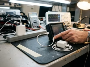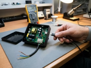
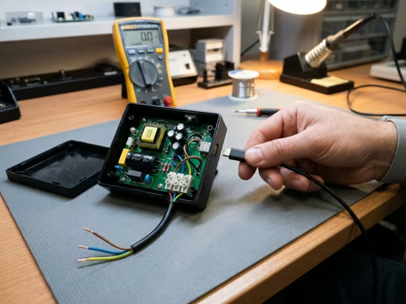
A smart thermostat runs on mains power. Its USB service port sits right under a technician’s fingers. Inside, one thin insulation layer separates that port from 230 V.
If that single layer fails, the port can carry a lethal voltage. Nothing on the outside warns anyone.
Isolation grades are not interchangeable. The wrong choice can fail certification or injure someone.
I review isolation designs with engineers and buyers every week. This guide explains what functional, basic, and reinforced insulation mean, what sets the right grade, and how to choose one without guessing.
What Isolation Really Does in a Power Supply
Most engineers know that isolation keeps the mains away from the output. That explains only part of its job. In practice, every isolation barrier blocks fault current, limits leakage, and protects outputs that look harmless. Each of those jobs changes how you design it.
It Blocks the Path a Fault Wants to Take
Isolation removes any direct conductive path between the primary and secondary circuits. Energy crosses the barrier through the transformer’s magnetic field. Feedback crosses through an optocoupler or a digital isolator.
That gap matters most when something breaks. Suppose a winding insulation layer cracks, or a fault shorts the optocoupler. Without a sound barrier, fault current flows straight to the output connector, and from there to the user.
So when I review a design, I don’t ask whether the output is isolated. I ask what happens when one part of the barrier fails.
It Also Controls Leakage Current
A barrier can block a fault and still let current leak across. The usual source is the Y-capacitor. Designers place it across the barrier to quiet EMI, and it carries a small AC current to the output every second the unit runs.
The numbers add up quickly. At 230 V and 50 Hz, a 2.2 nF Y-capacitor passes about 160 µA. IEC 62368-1 limits touch current on most ES1 outputs to 0.5 mA. Medical equipment sets much tighter limits, often 100 µA or less in normal operation.
That’s why Y-capacitors carry safety ratings. A Y2 part suits basic insulation. A Y1 part suits reinforced insulation. Pick the wrong class, and one shorted capacitor bridges the whole barrier.
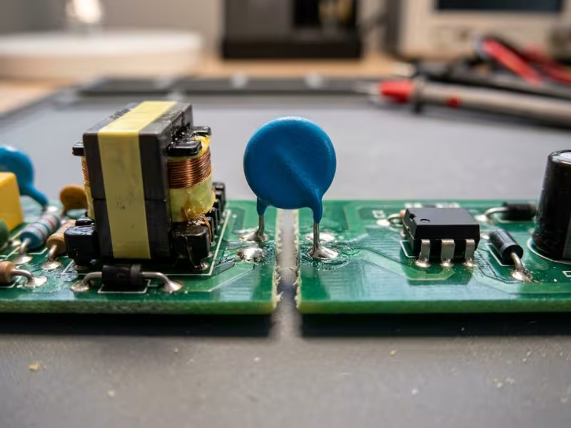
A 5 V Output Isn’t Automatically Safe
A low output voltage tells you nothing about fault safety. A USB charger delivers 5 V, but its bulk capacitor sits near 325 V on a 230 V line.
If the barrier fails, the secondary rises toward that primary voltage. The 5 V port then becomes a hazard, even though nothing about it looks dangerous.
Field wiring adds another risk. A sensor cable that runs next to mains conductors can pick up hazardous voltage after an installation fault. The output stays “safe” only because the barrier behind it holds.
Treat every touchable output as safe only after you prove the barrier can survive a single fault.
Functional, Basic, and Reinforced Insulation: What Each Grade Really Does
The three grades sound like steps on a voltage ladder. They aren’t. Each grade has a different safety job, and the standards treat a failure in each one differently. I explain them by asking a simple question: what happens to the user if this layer breaks?
Functional Insulation: It Keeps the Circuit Working, Nothing More
Functional insulation separates conductors so the circuit runs correctly. It keeps a 12 V trace away from a 3.3 V trace. It keeps the two ends of a fuse apart. It separates two signal grounds on the same side of the main barrier.
Its job is operation, not protection. If it fails, you might get a short, a blown fuse, or a burned trace. The standards don’t count it as a shock safeguard.
Never let functional insulation stand between a user and the mains. Many isolated DC-DC modules carry only functional isolation, even with a 1.5 kV test rating on the label. That module works well between two low-voltage domains. It can’t serve as your safety barrier.
Functional insulation still needs care, though. In a single-fault test, a lab may short it on purpose. The product must then fail safely, without fire or exposed hazardous voltage.
Basic Insulation: One Safeguard, With Earth as the Backup
Basic insulation gives one layer of shock protection. It never works alone. In Class I equipment, the protective earth provides the second layer.
A typical example is the gap between the primary circuit and a grounded metal chassis or heatsink. If that insulation breaks down, fault current flows to earth. The fuse or breaker opens before anyone touches a live case.
So basic insulation is safe only when the earth path is real. I’ve seen grounded designs shipped with a two-pin plug for one market. Others came with a chassis bonding screw that someone painted over. In both cases, the basic layer was suddenly the only protection.
For 230 V mains equipment, basic insulation typically needs about 2.5 mm creepage and a 1,500 VAC class hipot. Treat these as starting points, not rules. Your standard’s tables set the real numbers.
Reinforced Insulation: One Barrier Doing the Whole Job
Reinforced insulation is a single system that gives the same protection as two independent layers. It must protect the user alone, with no earth to catch a fault.
You find it in Class II equipment, such as phone chargers and laptop adapters with two-pin plugs. You also find it across the primary-to-secondary barrier of almost every AC-DC power supply with a touchable output.
That job costs space and effort. For 230 V mains, reinforced creepage roughly doubles to about 5 mm, and hipot rises to the 3,000 VAC class. Transformers often need triple-insulated wire, extra tape layers, or wide margin tape.
The biggest trap here involves parts that bridge the barrier. Reinforced insulation covers everything that crosses it, including the transformer, optocoupler, Y-capacitor, PCB slot, and even a mounting screw. One part rated only for basic insulation turns your reinforced barrier into a basic one.
You’ll also see “double insulation.” It means basic insulation plus a separate supplementary layer. The standards treat it as equal to reinforced. The difference lies in how you build it, not in how well it protects.
Grade | Main purpose | Protects against shock? | Typical use | If it fails… |
|---|---|---|---|---|
Functional | Lets the circuit operate correctly | No | Between traces, signal grounds, or fuse terminals | Malfunction or fire risk, with no shock protection lost |
Basic | Provides one layer of shock protection | Yes, but only with a second measure | Primary to earthed chassis in Class I equipment | Protective earth must clear the fault |
Reinforced | Provides full shock protection in one barrier | Yes, on its own | Class II products and primary-to-secondary barriers | Nothing else stands between the user and the mains |
The Fastest Way to Tell Which Isolation Grade You Need
Most grade mistakes start when a team picks the insulation first and justifies it later. I work in the opposite order. Five questions, asked in a fixed sequence, settle the grade for most barriers in about ten minutes.
The order matters, because each answer narrows the next one.
Start With Touchable Parts and Fault Paths
Question one: is the secondary touchable? Check every port, connector, screw, metal case, and cable that a user, installer, or service technician can reach. Include anything a test finger can reach through a vent or seam.
If nothing on the secondary side is accessible, functional or basic insulation may be enough. If a USB port, Ethernet jack, or sensor terminal sits on that side, the barrier now protects a person.
Next, trace the fault path. Draw a line from the mains to each touchable part. Every component that line crosses belongs to the barrier. That includes the transformer, optocoupler, Y-capacitor, PCB gap, and any mounting hardware.
Then Check the Earth and the Single Fault
Question two: is there protective earth? Count it only if three things exist: a three-wire cord, a rated bonding point, and a real connection to the touchable part. A grounded chassis won’t help if the USB port’s circuit never connects to it.
Question three: what happens under a single fault? Picture one insulation layer shorting. Test labs do this for real. If earth carries the fault current and the fuse opens, basic insulation plus earth can work. If the touchable part simply goes live, you need reinforced or double insulation.
Only Then Let the Standard Name the Grade
Question four: which standard governs the product? IEC 62368-1 covers most IT and AV equipment. IEC 61010-1 covers lab and test gear. IEC 60335-1 covers household appliances. IEC 60601-1 covers medical devices and uses MOOP and MOPP instead of basic and reinforced. The same barrier can need different spacing under each one.
Question five: does this barrier carry safety responsibility? Some barriers only provide functional separation. An isolator between two low-voltage domains behind a reinforced barrier usually needs only functional insulation. Move that same part to the mains side, and it needs a safety rating.
Design question | Why it matters | What it usually points to |
|---|---|---|
Is the secondary touchable? | Sets whether the barrier protects a person | Touchable means basic or higher |
Is there reliable protective earth? | Decides whether a second safeguard exists | Earth present: basic may work. No earth: reinforced |
What happens under a single fault? | Shows if a touchable part can go live | Goes live: reinforced or double |
Which standard governs the product? | Sets spacing, test voltage, and terms | Use that standard’s tables, not a generic rule |
Does the barrier carry safety responsibility? | Separates safety barriers from signal isolation | No safety role: functional is enough |
If two answers point in different directions, choose the higher grade for that barrier. Then confirm your choice with your test lab before layout starts. A short email at this stage can save you from a board respin later.
What Actually Sets the Isolation Requirement
The grade tells you what a barrier must do. Four other factors tell you how big that barrier must be. I see teams pick the right grade and still fail certification because they skipped one of these factors.
Each factor below changes your creepage, clearance, or test voltage.
Working Voltage Counts, Not the Marketing kV Number
Working voltage is the highest voltage the barrier sees in normal operation. It is often higher than the line voltage.
In a flyback adapter on 230 V mains, the primary-to-secondary barrier can see 400 V to 600 V peak once the reflected voltage and switching ringing add up. Measure it on the real board with a differential probe at high line and full load.
Peak working voltage mostly drives clearance. RMS working voltage drives creepage. A part’s “5 kV isolation” label describes a one-minute withstand test. It says little about the voltage the part can carry for years. On an optocoupler or digital isolator, check the rated working voltage, often listed as VIORM or VIOWM, and compare it with your measured peak.
Pollution Degree and Overvoltage Category Move the Numbers Fast
Overvoltage category describes the transients your product may face. OV I covers protected circuits. OV II covers plug-in equipment. OV III covers fixed installations, and OV IV covers the supply origin. On 230 V mains, the rated impulse rises from 2.5 kV at OV II to 4 kV at OV III. That change roughly doubles basic clearance, from about 1.5 mm to 3 mm.
Pollution degree describes the dirt and moisture on the board. PD1 means sealed or coated. PD2 fits homes and offices. PD3 fits factories with conductive dust or condensation. At 250 V on standard FR-4, basic creepage grows from about 2.5 mm at PD2 to 4 mm at PD3.
A DIN-rail supply in a factory panel can easily face OV III and PD3 at the same time. That is the costly combination.
PCB Material and CTI Change Creepage
The comparative tracking index (CTI) shows how well a material resists surface tracking. The standards sort materials into four groups:
- Group I: CTI 600 or higher
- Group II: 400 to 599
- Group IIIa: 175 to 399
- Group IIIb: 100 to 174
Standard FR-4 usually sits in group IIIa. If you can’t prove the CTI, labs often assume IIIb. A high-CTI laminate can cut required creepage nearly in half. At 250 V and PD2, basic creepage drops from about 2.5 mm to 1.25 mm. On a cramped charger board, that gain can save a slot or a larger housing.
The Standard Writes the Rulebook
IEC 62368-1 covers IT and AV equipment, including most ITE power supplies and external adapters. IEC 61010-1 covers lab and measurement gear, often with stricter OV categories. IEC 60335-1 covers household appliances. IEC 60601-1 covers medical devices.
Medical rules use different terms. MOOP protects operators, and MOPP protects patients. Two MOPP at 230 V means 4,000 VAC testing and about 8 mm creepage. Two MOOP sits much closer to standard ITE limits.
Factor | What it changes | Why designers miss it |
|---|---|---|
Working voltage | Creepage, clearance, and part ratings | They use line voltage, not the measured peak |
OV category and pollution degree | Clearance and creepage | They assume office conditions for industrial sites |
CTI material group | Required creepage | They never confirm the laminate’s CTI |
Governing standard | Test voltage, spacing, and terms | They copy limits from a different standard |
Pin down all four factors before you start layout. A wrong guess here usually shows up as a failed spacing review.
How Isolation Gets Verified in the Real World
A test report can make a barrier look stronger than it is. Most of the isolation problems I catch come from reading a pass result as more than it proves. Three misunderstandings cause most of the trouble.
A Hipot Pass Proves Short-Term Strength, Not Long Life
A dielectric withstand (hipot) test applies a high AC or DC voltage across the barrier, often for 60 seconds. If the leakage current stays under the trip limit and nothing arcs, the barrier passes.
That result tells you the insulation survived one minute of stress on that day. It doesn’t tell you how the barrier will hold up after years of heat, humidity, and switching spikes.
Thin insulation can pass hipot and still suffer partial discharge: tiny sparks inside voids in the material. Those sparks slowly eat through tape, potting, or an optocoupler’s internal layer. For that reason, standards often require partial discharge testing on reinforced parts with thin solid insulation. Many isolator datasheets list it under IEC 60747-5-5.
So a “5 kV tested” barrier isn’t automatically reinforced. It has simply survived a test.
Spacing Review Carries as Much Weight as Component Ratings
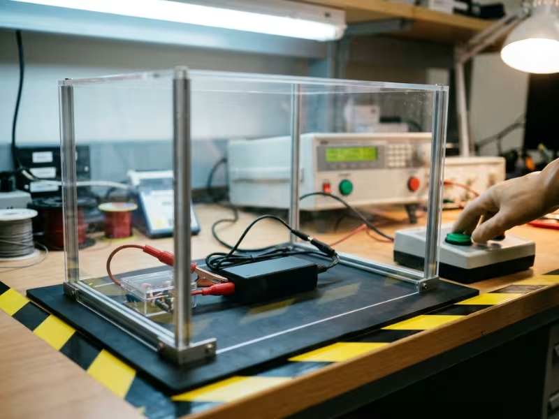
Hipot mainly stresses solid insulation and air gaps. It barely checks creepage, because creepage protects against surface tracking that builds up over time with dust and moisture.
I’ve seen a board pass 4 kV hipot with only 3 mm of creepage across a 230 V reinforced barrier. On a clean lab bench, it held. Under the standard’s tables, it needed about 5 mm, so it failed the spacing review.
Measure creepage and clearance on the real layout before you send samples to the lab. Check every point where the barrier gets narrow, such as optocoupler pins, Y-capacitor pads, transformer pins, and mounting screws. Labs measure these with calipers and gauges, and they won’t accept “the parts are rated for it.”
Type Testing and Production Testing Answer Different Questions
Type testing proves the design. The lab tests a few samples, often after 48 hours or more of humidity conditioning. It runs the full hipot, checks spacing, and performs single-fault tests.
Production testing proves the build. The factory hipots every unit, usually for 1 to 2 seconds, to catch a pinched wire, a solder bridge, or a missing tape layer.
Neither test replaces the other. A clean production log can’t stand in for certification evidence. A certificate also can’t protect you if a factory changes the transformer tape without telling anyone.
Ask your supplier for both, and confirm that the production hipot voltage still matches the certified design.
Choosing the Right Isolation Strategy by Product Type
Grade definitions only help once you apply them to a real product. In my design reviews, most projects fit one of four patterns. Each pattern puts the hazard in a different place, so each one needs a different barrier.
For every scenario, I ask the same four questions. Where does the hazard sit? Which barrier protects the user? What grade does that barrier need? Where do teams usually slip?
Offline Wall Adapter With a Touchable Output
The hazard sits on the primary side: about 325 V DC on the bulk capacitor at 230 V input. The user holds the USB-C plug or barrel jack every day. Phone chargers, laptop adapters, and USB PD chargers all fit this pattern.
A two-pin adapter has no earth, so it falls under Class II. The primary-to-secondary barrier carries the full safety job, and it needs reinforced or double insulation. Every part that crosses that barrier needs the same rating:
- Transformer windings with triple-insulated wire or enough tape layers
- An optocoupler rated for reinforced insulation at your working voltage
- A Y1 capacitor, not a Y2
- The PCB slot under the transformer and optocoupler
The usual slip comes when a team designs a three-pin version first and then adds a two-pin model. In the three-pin design, earth backs up a basic barrier. Remove the earth pin, and that barrier must suddenly do the whole job. I also check metal USB-C shells and screws near the transformer. Either one can shrink creepage below the reinforced limit.
Grounded Industrial Controller With Field Wiring
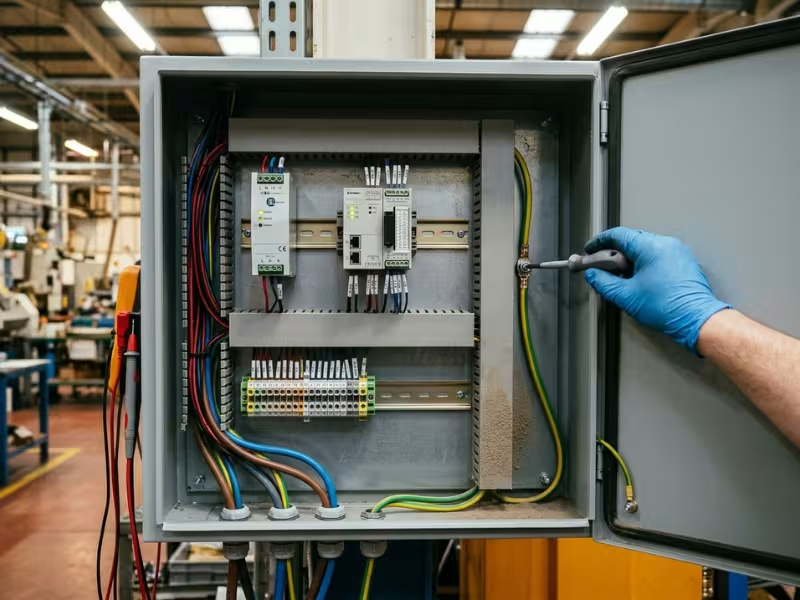
The mains enters a metal enclosure, and 24 V field wiring runs out to sensors and actuators. An installer, not the end user, usually touches those terminals.
This product counts as Class I. Basic insulation from the primary to the earthed chassis is a legitimate design choice, because protective earth catches a fault. The earth only helps if it works. I check for:
- A dedicated PE terminal with a proper wire gauge
- Bonding screws that cut through paint or anodizing
- A low-resistance path from every touchable metal part to PE
Teams often treat a DIN-rail clip or a signal ground as protective earth. Neither one qualifies. I also see field cables routed beside mains conductors in the same duct. An installation fault can push hazardous voltage onto “safe” I/O terminals, so plan for OV III and PD3 conditions in the panel.
Medical or Patient-Adjacent Equipment
Here the hazard is the same mains voltage, but the person at risk may be a patient. That patient may have sensors on the skin or near the heart, and less ability to react to a shock.
IEC 60601-1 applies here. Any barrier between the mains and a patient applied part usually needs 2×MOPP. At 230 V, that means 4,000 VAC testing and about 8 mm creepage. Leakage limits also tighten. A Type BF applied part allows 100 µA of patient leakage in normal operation. A Type CF part allows only 10 µA.
For any product with an applied part, choose a medical power supply certified for 2×MOPP, not just 2×MOOP. The common slip happens when a team buys a 2×MOOP supply, then adds a patient sensor later. The supply no longer fits the product. A Y-capacitor that suited an ITE design can also push leakage over the medical limit on its own.

Internal Signal Isolation Behind the Main Barrier
Many products include a second isolator, such as an isolated DC-DC converter feeding an RS-485 port or a digital isolator between logic domains.
If both sides already sit behind a sound reinforced barrier, this isolator carries no shock protection role. Functional insulation is usually enough. It only needs to handle ground noise and common-mode voltage.
The slip comes when one side ties to the mains. Energy meters and power monitors often reference their measurement front-end to line voltage. In that case, the “signal” isolator becomes the safety barrier, and a functional part can’t fill that role.
Scenario | Safety concern | Typical insulation choice | Common mistake |
|---|---|---|---|
Offline wall adapter | Mains reaching a handheld output | Reinforced primary to secondary, Class II | One basic-rated part bridging the barrier |
Grounded industrial controller | Fault voltage on chassis or field terminals | Basic to earth, plus reliable PE | Counting a DIN-rail clip or signal ground as earth |
Medical equipment | Shock or leakage through a patient | 2×MOPP for patient contact | Using a 2×MOOP supply with an applied part |
Internal signal isolation | Ground noise between low-voltage domains | Functional, behind a reinforced barrier | Using it where one side ties to the mains |
Common Mistakes That Break Isolation Assumptions
Most isolation failures I see don’t come from bad parts. They come from good parts used on the wrong assumption. Four mistakes cause most certification failures and board respins on the projects I review.
A High-Rated Component Doesn’t Make the System Compliant
A reinforced-rated optocoupler might offer 8 mm of creepage across its own package. Solder it onto a board with 3 mm between the primary and secondary pads, and your barrier now has 3 mm. The board sets the limit, not the part.
Transformers work the same way. A certified transformer still depends on how you mount it. A flying lead, a heatsink clip, or a ground trace routed under the bobbin can shrink the spacing the certificate assumed.
Component certificates also carry conditions of acceptability. These cover the working voltage, temperature, and pollution degree the lab accepted. Read them before you treat the part as a finished safety barrier.
“5 kV Isolation” Is a Test Result, Not a Grade
A large kV number on a datasheet usually describes a one-minute withstand test. It doesn’t tell you whether the part is functional, basic, or reinforced.
Many isolated DC-DC modules advertise 3 kVDC or more and still offer only functional insulation. The units matter as well. A 3 kVDC test equals only about 2.1 kVAC.
For a reinforced barrier, look for three things on the datasheet:
- The word “reinforced”
- A rated working voltage, such as VIORM, that covers your measured peak
- A certificate under the standard you plan to use
A UL 1577 rating alone gives you a withstand voltage. It doesn’t give you an insulation grade.
A PCB Slot Can’t Fix the Wrong Safety Concept
Slots help. They lengthen the surface path and can rescue a tight creepage problem. But they have limits.
A slot narrower than about 1 mm at pollution degree 2 doesn’t count at all. The standard assumes dirt bridges it. A slot also does nothing for clearance, which the straight-line air gap sets.
More importantly, no slot can upgrade a basic-rated Y-capacitor or optocoupler that bridges a reinforced barrier. I’ve seen teams cut slot after slot to chase a creepage number. The real fix was a different part or a different grade from the start.
Low Voltage Doesn’t Always Mean Low Hazard
A 12 V rail sounds harmless. But if a primary-side auxiliary winding generates it, that rail sits at mains potential. Anything you connect to it does too.
Smart plugs and small appliances often use a capacitive dropper or a non-isolated buck converter. The whole control board, including its “3.3 V” logic, then floats at line voltage. A debug header or a sensor lead from that board needs full mains-level insulation.
Before you call any circuit safe, ask what it connects to, not just what voltage it runs at.
Each of these mistakes looks small on a schematic. In the lab, any one of them can fail the entire barrier.
FAQ
These six questions come up in nearly every isolation review I join. Here are the short answers I give engineers and buyers.
What is the difference between basic and reinforced isolation?
Basic insulation gives one layer of shock protection, and protective earth backs it up. Reinforced insulation protects the user on its own, with no earth behind it. On 230 V mains, creepage roughly doubles, from about 2.5 mm to 5 mm. The hipot also rises from the 1,500 VAC class to the 3,000 VAC class.
Is double insulation the same as reinforced insulation?
The two offer the same protection, and IEC standards treat them as equal. They differ in how you build them. Double insulation stacks two separate layers, basic plus supplementary, and you can test each one. Reinforced insulation uses one system, such as triple-insulated wire, that does both jobs at once.
What does 2×MOPP mean on a medical power supply?
It means the supply gives two means of patient protection under IEC 60601-1. At 230 V, that calls for 4,000 VAC testing, about 8 mm creepage, and tight leakage limits. You need it when your product has a patient applied part. A 2×MOOP supply only protects operators, so it won’t cover a patient sensor you add later.
How do I know which isolation grade my product needs?
Start with the touchable parts. Ask three questions. Can someone reach the secondary? Does real protective earth exist? What happens if one layer shorts? If a touchable part goes live with no earth to catch the fault, you need reinforced insulation. Then take the exact spacing from your governing standard and confirm it with your test lab before layout.
What is the difference between creepage and clearance?
Clearance is the shortest path through air. Creepage is the shortest path along a surface. Peak voltage and overvoltage category drive clearance, because air gaps fail from spikes. RMS voltage, pollution degree, and CTI drive creepage, because surfaces fail from dust and moisture over time. A PCB slot lengthens creepage but does nothing for clearance.
Can I use a basic-isolated component in a reinforced isolation slot?
Not on its own. Every part that bridges a reinforced barrier needs a reinforced rating. That includes the transformer, optocoupler, Y1 capacitor, and even mounting screws. One basic-rated part drops the whole barrier to basic. The only workaround I accept is a separate, tested supplementary layer that backs that part up, forming double insulation. Clear that with your lab first.
Choose the Isolation Grade Before Layout Starts
Isolation grade follows the safety job a barrier does. A “5 kV” label can’t tell you whether you need functional, basic, or reinforced insulation. The touchable parts, the earth path, and the single-fault outcome tell you that.
Once you know the grade, three things set the real numbers: the governing standard, your measured working voltage, and the site environment. Together, they decide your creepage, clearance, test voltage, and which parts can cross the barrier.
Timing decides the cost. On a schematic, a grade change takes an afternoon. After layout, it can force a new transformer, a wider board, a bigger housing, and a second round at the test lab.
So before you place a single part, pull the insulation tables from your standard. Then mark every barrier on the schematic with its grade and required spacing.