
If you’ve owned electronics for a couple of decades, you remember the old wall adapters — heavy black bricks that ran warm, hogged the outlet beside them, and weighed nearly as much as a paperback novel. Today, a 65W charger that can power a full laptop fits in your jacket pocket and barely gets warm to the touch. The outlet didn’t change. The electricity didn’t change. What changed is what’s happening inside the box. Almost everything now runs on a switching power supply, and once you understand how one works, you’ll see them everywhere.
This guide walks through that change in plain language. You’ll learn what a switching power supply is, its six components, how electricity moves through it step by step, and why it outperforms the older linear design in nearly every modern application. We’ll also cover how to read a charger label and what you actually need to know to stay safe. No engineering background required. If you can picture a kitchen faucet, you can follow this.
Why Switching Power Supplies Are Everywhere
Your wall outlet delivers alternating current (AC) at about 120V in the US. The chips inside your phone, laptop, and TV need something completely different: low-voltage direct current (DC), typically 5V, 12V, or 20V — and often less than 1V for the processor itself. Something has to make that conversion reliably, every second the device is on. In nearly every modern product, that something is a switching power supply.
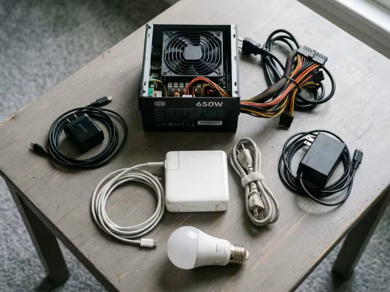
You probably own more of them than you realize:
- Phone and USB-C chargers, including compact multi-port GaN chargers
- Laptop power bricks, from a 45W ultrabook adapter to a 240W gaming charger
- Desktop PC power supplies (PSUs), the metal box with the fan at the rear of your tower
- LED light bulbs, which conceal a small driver circuit inside the base
- TVs and game consoles, which integrate the power supply directly onto an internal board
They replaced older designs for one fundamental reason: they waste very little energy. Less waste means less heat, and less heat means smaller, lighter hardware. Once manufacturing costs came down, the case for the old heavy brick simply collapsed.
What Is a Switching Power Supply?
A switching power supply converts electricity by turning a transistor fully on and fully off — tens of thousands to millions of times per second. It then smooths those rapid pulses into steady DC at exactly the voltage your device needs. Engineers call it an SMPS (switched-mode power supply). That abbreviation appears constantly on datasheets and in product specs, and it always means the same thing.
The most intuitive way to understand it is with a faucet. Suppose you want to fill a glass at a slow, steady rate. One approach is to open the faucet just a crack. It works, but it’s imprecise and hard to control. The other approach sounds counterintuitive: flick the faucet fully open and fully shut, over and over, very fast. If it’s open half the time, you get half the flow. Want more water? Leave it open a little longer each cycle. A switching power supply uses exactly this logic. It never “half opens” its switch. It controls output power purely by adjusting how long the switch stays on each cycle. And here’s the critical part: a switch that is fully on or fully off wastes almost no energy. All the losses occur in the transition between states, and a switching supply spends as little time there as possible.
Switching vs. Linear Power Supplies
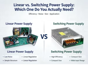
Before switching supplies took over, most adapters used linear power supply designs. A linear supply steps AC voltage down with a large transformer running at the grid’s 60 Hz, then a voltage regulator removes the excess by converting it into heat. The analogy holds well: it’s like holding your car’s speed constant by keeping the accelerator floored and riding the brake. You’ll stay at the speed you want, but you’ll burn fuel doing it.
The numbers are revealing. Say a linear regulator must convert 12V to 5V for a device drawing 1A. The load consumes 5W. The regulator dissipates 7V × 1A = 7W as heat — roughly 42% efficiency, meaning most of the input energy heats the room rather than powering the device. A switching supply handling the same conversion typically reaches 85–95% efficiency, wasting well under 1W.
Factor | Linear | Switching |
|---|---|---|
Typical efficiency | ~30–60% (varies with voltage drop) | ~80–95% |
Size and weight | Large, heavy 60 Hz transformer | Compact and light |
Heat output | High | Low |
Electrical noise | Very low | Higher; requires filtering |
Design complexity | Simple | More complex |
Common applications today | Audio equipment, lab instruments | Chargers, PCs, LEDs, TVs |
Linear supplies aren’t dead. Audiophiles and test engineers still reach for them because they produce almost no switching noise. For nearly everything else, the trade-off is straightforward: switching supplies accept marginally more electrical noise in exchange for dramatic gains in efficiency, size, and thermal performance. That’s a deal almost every product designer takes.
The Key Components of a Switching Power Supply
Most wall-powered switching supplies share the same six building blocks. The list below follows signal flow — the order electricity actually moves through the circuit. Reading it this way makes the step-by-step walkthrough in the next section much easier to follow.
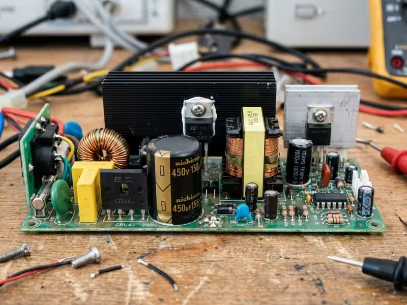
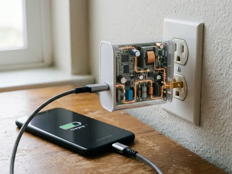
- Input filter and rectifier. The first stage does two things. An EMI (electromagnetic interference) filter prevents the supply’s high-frequency switching noise from leaking back into the building wiring, where it could affect other equipment. Then a bridge rectifier — four diodes arranged in a loop — flips the negative half of each AC cycle so current always flows in one direction. The output is pulsating DC.
- Bulk capacitor. This large capacitor, often the physically biggest component on the board, smooths the pulsating DC into a stable high voltage. On a US 120V circuit, that works out to roughly 170V DC, because AC voltage peaks well above its rated value. This capacitor stores real energy. That matters for the safety discussion below.
- Switching transistor (MOSFET). This is the faucet. It switches on and off at high frequency — typically 50 kHz to over 1 MHz. Many newer chargers replace traditional silicon MOSFETs with GaN (gallium nitride) transistors. GaN devices switch faster and lose less energy during each transition. That’s the core reason GaN chargers can be so much smaller than their silicon predecessors.
- High-frequency transformer or inductor. This component steps the voltage down — from roughly 170V to, say, 20V. In any supply that connects to a wall outlet, the transformer also provides isolation: there is no direct electrical path between the mains side and the output cables. Energy transfers across a magnetic field, and hazardous voltage cannot follow it.
- Output rectifier and filter. Additional diodes and capacitors convert the high-frequency pulses back into smooth, low-voltage DC. A small residual variation always remains — engineers call it ripple, the slight wobble riding on top of the DC output. Quality supplies keep ripple tightly controlled. Budget units often don’t, which can affect sensitive downstream electronics.
- Feedback and control circuit. This is the intelligence of the supply. A PWM (pulse-width modulation) controller chip monitors the output voltage continuously and adjusts the transistor’s on-time in real time. Because the output side is electrically isolated from the input side, the feedback signal crosses the gap via an optocoupler — a device that transmits the correction signal as light across a tiny internal gap, using a miniature LED and photodetector sealed in one package.
How a Switching Power Supply Works, Step by Step
Let’s trace the electricity from your wall outlet to your phone, using a standard USB charger as the example.
- AC enters and is filtered. Power arrives at 120V AC, alternating at 60 times per second. The EMI filter cleans the incoming waveform and blocks the charger’s own switching noise from escaping back into the wall.
- It becomes high-voltage DC. The bridge rectifier redirects the AC waveform into one direction. The bulk capacitor smooths the result into roughly 170V of steady DC. At this stage, you have high voltage inside a device that will ultimately deliver 5V to your phone—which is also why the same charger works in Japan, Germany, and Brazil. Its input range spans the full global spectrum.
- The transistor chops it into fast pulses. The MOSFET switches that 170V DC on and off — 100,000 times per second in a typical design. What was a flat DC line becomes a rapid square wave, like water pulsing from a faucet flicked open and shut at high speed.
- The transformer steps it down and isolates it. High-voltage pulses on the primary side produce proportionally lower-voltage pulses on the secondary side. No wire bridges the two sides. Energy crosses through the magnetic core. The wall’s voltage stays on the input side, away from the cable you handle.
- The output is rectified and smoothed. Diodes and capacitors on the output side convert those pulses into steady DC — 5V for a standard charger, or up to 20V for a USB-C PD charger negotiating with a laptop.
- Feedback corrects it in real time. This is the step that makes a regulated supply actually regulated. When your phone enters fast charge mode and draws more current, the output voltage dips. The controller detects this within microseconds and extends the transistor’s on-time slightly until the voltage returns to target. When load decreases, it shortens the on-time. This loop never stops while the supply is operating.
Duty Cycle: The Secret to Precise Voltage
The fraction of each switching cycle during which the transistor stays on is the duty cycle, expressed as a percentage. At a 30% duty cycle, the switch is on for 30% of each cycle and off for the remaining 70%. Back to the faucet: the longer it stays open per flick, the more water flows per second. Duty cycle is the singular control variable behind everything a switching supply does.
The clearest demonstration comes from a buck converter — a basic non-isolated topology that steps voltage down. Ideally, output voltage equals duty cycle times input voltage. A 50% duty cycle on 12V produces about 6V. A 25% duty cycle produces about 3V. Real circuits lose some accuracy to resistance and switching losses, so the numbers never land exactly on target. That’s what the feedback loop is for: it continuously nudges the duty cycle until the output holds its specification. When a spec sheet says “regulated output,” this is the mechanism being described.
Why Higher Frequency Means a Smaller Charger
This is what explains the shrinking adapter more directly than any other single factor. A transformer must handle the energy delivered in each switching cycle. At 60 Hz (the old linear approach), each cycle is long and carries a large burst of energy, so the transformer core has to be physically large enough to absorb it. At 100 kHz, each cycle is over 1,600 times shorter and carries a proportionally smaller energy packet. Smaller packets need smaller cores. Push the frequency higher and the transformer, along with its filtering capacitors, can shrink substantially. GaN transistors extend this further: they switch at higher frequencies with lower switching losses, so designers can keep going without hitting a thermal wall. That’s the complete engineering story behind the journey from a heavy black brick to a pocket-sized cube — faster switching, smaller passive components, and transistors that handle the speed without overheating.
Common Types of Switching Power Supplies
Engineers refer to different circuit architectures as topologies. Dozens exist in practice, but four cover most of what you’ll encounter as a consumer or when sourcing ITE power supplies for equipment.
Topology | What it does | Where you’ll see it |
|---|---|---|
Buck | Steps voltage down | Inside laptops and phones; converts battery voltage to ~1V for processors |
Boost | Steps voltage up | Power banks (3.7V cell to 5V USB output), LED drivers |
Buck-boost | Steps voltage up or down | Battery-powered devices where cell voltage swings above and below the target |
Flyback | Isolated; steps up or down | Most phone and laptop chargers up to roughly 100W |
The most important dividing line is isolated vs. non-isolated. Any supply drawing power from a wall outlet must be isolated — a transformer keeps dangerous mains voltage physically separated from the output terminals and cables you touch. That’s why the flyback topology dominates consumer chargers: it’s inherently isolated, relatively straightforward to design, and cost-effective to manufacture. Converters operating inside a device (such as the buck regulator delivering 1V to a processor from a 5V rail) work from safe low-voltage sources and need no isolation, so they omit the transformer and stay compact. At higher power levels — an 850W desktop PSU, for instance — designers shift to more advanced isolated topologies like forward converters or LLC resonant designs to maintain efficiency at scale. The underlying principle doesn’t change. The same switching logic that runs a 5W phone charger also runs a data center power shelf.
How to Read a Power Supply Label
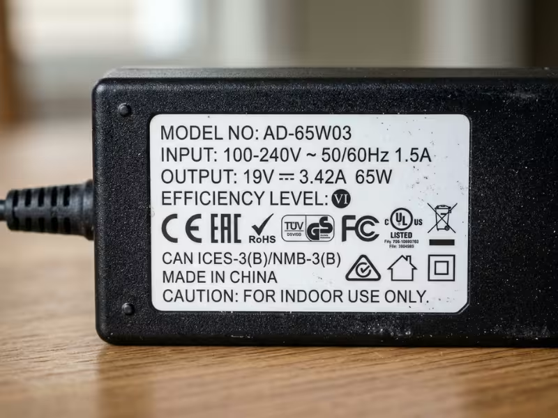
Every adapter and power supply carries a label with the same core specifications, usually printed in small gray text on the back or underside. Here’s what each line actually means, using a 65W laptop adapter as the example.
- Input: 100–240V ~ 50/60 Hz. This supply accepts any household voltage standard on Earth. You need a plug-shape adapter when traveling internationally, not a voltage converter. This broad input tolerance is a direct consequence of the switching topology — an old linear brick was typically hardwired to one country’s voltage.
- Output: 20V ⎓ 3.25A. The DC output voltage and maximum deliverable current. The ⎓ symbol denotes DC.
- Wattage: 65W. Voltage times current: 20 × 3.25 = 65W. This is the continuous power ceiling.
- Efficiency mark. US-market external adapters typically carry a DOE Level VI mark. Desktop PSUs use 80 PLUS ratings — Bronze, Silver, Gold, Platinum, Titanium — in increasing order of efficiency at various load points.
- Safety certifications. UL, ETL, and CE indicate the design has been evaluated against established safety standards. An adapter with no recognizable mark is a meaningful warning sign.
When sourcing a replacement, work through these four checks in order:
- Voltage must match exactly. A laptop rated for 19V is not tolerant of 18V or 20V in most cases. USB-C PD chargers are an exception — they negotiate voltage dynamically with the device before delivering power.
- Current rating must meet or exceed the device’s requirement. A 4A adapter powering a 3A device is fine. Reversing the polarity will trigger thermal shutdown or damage the adapter.
- On barrel connectors, check polarity and diameter. Most adapters have a small diagram showing whether the center pin is positive or negative. Reversed polarity can destroy downstream electronics immediately.
- Confirm a recognized safety certification. A $9 unbranded adapter and a $45 certified one can print identical specs. What’s inside is often not the same.
Switching Power Supply Safety and Lifespan
Certified switching power supplies are safe for everyday use. Well-designed units incorporate layered protection: overvoltage, overcurrent, short-circuit, and over-temperature shutdown. A quality supply responds to output faults by shutting itself down, not by passing the problem through to your device. For applications with stricter regulatory requirements — clinical equipment, for instance — designs must meet additional standards; medical power supplies carry specific certifications (IEC 60601) that general-purpose adapters do not.
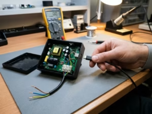
One hazard deserves a clear warning: don’t open wall-powered supplies. The bulk capacitor can retain approximately 170V DC (around 325V on 230V supplies) for several minutes after unplugging — sometimes considerably longer. That stored energy is enough to cause a serious shock. If a supply is faulty, replace it rather than attempting a repair unless you have proper training and discharge procedures.
Common Myths, Debunked
Myth #1: A charger with a higher amp rating will damage my device.
Your device determines how much current it draws. A 5A charger connected to a phone that requests 2A delivers exactly 2A. Amperage on the label is a maximum capacity, not a fixed output. What must match is the voltage. Current is a ceiling; the device sets the floor.
Myth #2: Two chargers with the same label specs are equally safe.
The label describes what a charger is designed to deliver — not how it was built. Cheap uncertified units frequently cut corners on creepage distance (the physical gap between mains and output conductors) and omit protection circuitry. Teardowns of counterfeit adapters routinely show isolation gaps a fraction of what safety standards require. Certification marks are your most accessible proxy for build quality.
Myth #3: A faint high-pitched whine means the supply is defective.
That sound — coil whine — is magnetic material in the transformer or inductors vibrating at the switching frequency. It’s almost always harmless and often varies with load. Signs that require action include a burning smell, a visibly swollen or cracked enclosure, flickering output voltage, or noise that grows louder over time. Any of those means unplug and replace.
What Wears Out, and How to Slow It Down
In most switching power supplies, the component most likely to fail first is the electrolytic capacitor. Its liquid electrolyte gradually evaporates, a process that heat accelerates sharply. A widely cited approximation in thermal engineering is that electrolytic capacitor life roughly doubles for every 10°C reduction in operating temperature. A supply that runs at 45°C instead of 55°C can be expected to last approximately twice as long. Heat is the dominant variable, and most practical longevity measures come down to thermal management:
- Don’t cover adapters. A laptop brick buried under a bag or pillow can’t dissipate heat, and internal temperatures climb fast.
- Keep PSU fans and intake vents free of dust. Even a moderate dust buildup can raise internal temperatures noticeably.
- Leave headroom on rated wattage. A 750W PSU consistently powering a 600W load runs cooler and lasts longer than the same unit pushed to 90% capacity for hours.
- Use surge protection. Input voltage spikes stress the input filter, rectifier, and bulk capacitor — all components near the front of the signal path.
The Bottom Line on Switching Power Supplies
Every switching power supply operates on the same three-step logic: switch fast to chop high-voltage DC into rapid pulses; transform to step those pulses down through a small, isolating magnetic core; smooth and correct to filter the output into stable DC while a feedback loop adjusts duty cycle thousands of times per second. That sequence is why your charger shrank from a paperback-sized brick to something that fits beside your keys. Faster switching shrinks the passives. Near-zero losses eliminate the need for bulk heat management. The physics compounds.
The most practical thing you can do with this knowledge right now: pick up the nearest charger and read the label. Find the input voltage range, the output spec, the wattage, and the certification marks. Check it against the four criteria above. Once you can decode one label confidently, you can evaluate any power supply — and that’s a genuinely useful skill whether you’re buying a replacement adapter or specifying components for a product. For custom power supply requirements across a wide range of applications, explore our full product range.