A converter can look perfect on a datasheet and still fail in real use. I’ve seen units run hot inside sealed boxes, derate on summer afternoons, restart every time a motor kicks on, and fail safety reviews weeks before launch. Every one of them looked fine on paper.
The problem rarely starts with a bad part. It starts when buyers compare headline numbers and skip the conditions behind them.
This guide covers the nine specs that decide whether a converter will actually work in your device. They don’t carry equal weight, so I won’t treat them that way. You’ll see what to check first, which numbers people misread most, and how to narrow a long list down to two or three strong options before you compare prices.
Start With Your Device, Not the Datasheet Highlights
A datasheet’s first page shows a converter at its best. Those headline numbers usually assume 230 VAC input, 25°C air, an open bench, and a steady load. Your device rarely offers any of those conditions.
That’s why the same 60 W converter can run cool in one product and shut down in another. The converter stays the same. The device around it changes.
So before I open a single datasheet, I write down six facts about the device. Each one rules out converters quickly.
- Input region. Where will the device plug in? A product sold only in Europe can use a 180–264 VAC input. A product shipped to the US, Japan, and Brazil needs universal input, 90–264 VAC at 50/60 Hz. On weak grids, brownouts near 90 V can trip a narrow-input unit.
- Output voltage and continuous current. Measure the real draw, not the nameplate value. A 12 V board that pulls 1.6 A in idle mode may pull 2.5 A with every feature running.
- Peak load. Motors, solenoids, heaters, and large capacitor banks pull surges at startup. A pump that runs at 2 A may need 6 A for 200 ms. If the converter can’t hold that peak, it hiccups or restarts.
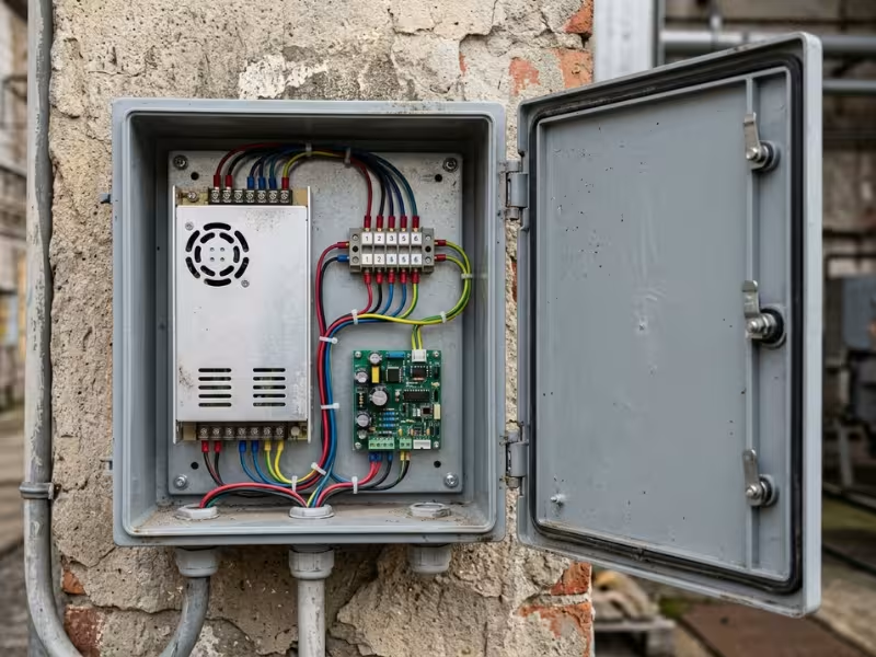
- Enclosure type. Will the converter sit in a sealed plastic box, a vented metal chassis, a DIN rail cabinet, or on an open shelf? A fanless sealed box can cut usable power by 30% or more.
- Ambient temperature. Measure the air around the converter, not the room. A control cabinet in a sunny warehouse can reach 50°C inside. Many converters start to derate at 40–50°C.
- Safety and compliance needs. Is this IT equipment, a household appliance, a lab instrument, or a medical device? Each one points to a different standard: IEC 62368-1, IEC 60335, IEC 61010, or IEC 60601-1. A converter certified to the wrong standard can force a retest.
Here’s how this plays out. Two customers once asked me about the same 24 V, 100 W enclosed converter.
The first customer mounted it in a ventilated rack at 25°C and drew a steady 80 W. It ran for years without a problem.
The second customer put it in a sealed outdoor box that reached 55°C, with a motor that doubled its current at startup. At 55°C, the unit derated to about 70 W. The startup surge pushed it into protection every morning.
Same part, two very different results.
Put your six answers on one page and use that page as a filter. Any converter that misses a single line drops off your list before you compare prices across different power supply products.
The First Three Specs That Decide Basic Fit
Not all nine specs carry the same weight. Three of them decide whether a converter can power your device at all: the input range, the output voltage, and the output current.
If a unit fails any of these, nothing else on the datasheet can save it. So I check them first.
Input Voltage Range and Line Frequency
Input range tells you where your device can plug in and keep working. Most converters fall into two groups:
- Universal input, usually 90–264 VAC or 85–264 VAC, which covers almost every grid in the world.
- Fixed or narrow input, such as 100–120 VAC or 180–264 VAC, sometimes with a manual selector switch.
For any product sold in more than one region, I choose universal input by default. The price gap is small today. One part number for every market also makes stock, service, and certification much simpler.
A narrow input still makes sense for single-region equipment at higher power. A 230 VAC-only design can use smaller input parts and sometimes runs a little more efficiently.
The bigger risk is low line. Grids sag during heavy use, and sites with long cable runs sag even more. A 100 VAC supply in Japan can drop to 90 V. Some regions dip into the low 80s during brownouts.
So I look past the headline range and check two details:
- Output at low line. Many universal units derate below 100 VAC. A 100 W converter might deliver only 80 W at 90 VAC. Look for a derating curve against input voltage, not just temperature.
- Brownout behavior. A good unit shuts down cleanly when input falls too low and restarts without help. A weak unit may chatter on and off, which can corrupt data or stress downstream parts.
Line frequency rarely causes trouble. Most converters accept 47–63 Hz, which covers 50 Hz and 60 Hz grids. Portable generators can drift outside that window under changing loads, though. If your device will run on generator power, confirm the frequency tolerance and test on the real generator.
Output Voltage and Regulation Accuracy
Picking the output voltage is easy. Common rails are 5 V, 12 V, 24 V, and 48 V, and most units let you trim the output by about ±10%. The harder question is how tightly that voltage needs to hold.
Regulation describes how far the output moves across changes in setpoint, line, and load. A 12 V output at ±5% can sit anywhere from 11.4 V to 12.6 V. For many loads, that window works fine.
Standard tolerance, around ±3–5%, usually works for:
- LED drivers, fans, and relay coils
- Motors and solenoids
- Boards that feed their own onboard regulators
Tighter regulation, around ±1–2%, matters when the converter output feeds a sensitive load directly:
- Analog sensors and ADC references with no local regulator
- Battery charging, where a small voltage error shortens battery life or leaves the battery undercharged
- Laser diodes and precision instruments
Before you pay for a tighter spec, check what sits after the converter. If your board has its own LDO or point-of-load regulator, a standard ±5% converter usually does the job.
Cable drop catches many people out. Picture a 24 V supply feeding 5 A through 3 m of 18 AWG wire. The 6 m round trip drops about 0.6 V before the power reaches the load. That error is bigger than the regulation spec. For long runs, use thicker wire or choose a converter with remote sense.
Multi-output converters need extra care. Usually only the main rail gets full regulation. The auxiliary rails follow it through cross-regulation. If the main rail runs light while an auxiliary rail runs heavy, that auxiliary voltage can drift 5–10% off target.
Many units also need a minimum load on the main rail to stay in spec. Read the cross-regulation table, and test your real load mix on the bench.
Output Current, Peak Load, and Power Headroom
Current is where I see the most sizing mistakes. The datasheet usually lists a continuous rating and, sometimes, a peak rating. They mean very different things.
- Continuous current is what the converter can deliver all day at the stated temperature.
- Peak current is a short burst, often 150% of the continuous rating for a few hundred milliseconds or a few seconds.
Always read the time limit next to the peak number. “200% peak” for 100 ms won’t start a pump that needs its surge for 500 ms.
Also check the maximum capacitive load. A board with a large capacitor bank can look like a short circuit at startup and push the converter into hiccup mode.
My sizing rule is simple. Run the continuous load at 70–80% of the converter’s rating. That leaves 20–30% headroom for part tolerance, aging, and the loads you’ll add later.
Here’s a real example. A 12 V control box has these loads:
- Main board: 2.0 A
- Cooling fan: 0.3 A
- LED indicator strip: 0.5 A
- Door-lock solenoid: 1.5 A, for about 300 ms when it fires
The continuous load is 2.8 A, or 33.6 W. Add 25% headroom, and you need about 42 W. A 12 V, 4 A (48 W) unit looks right.
Now add the peak. When the solenoid fires, the total hits 4.3 A for 300 ms. That’s above the 4 A rating. You have two clean options:
- A 48 W unit with a rated peak of at least 4.5 A for 500 ms or longer
- A 60 W unit, which covers the surge with continuous capacity
I usually choose the 60 W unit when the price gap is small. It runs cooler, and it doesn’t rely on a peak spec that some suppliers measure loosely.
Don’t swing too far the other way, though. A 150 W converter running a 35 W load wastes money and space. It may also run less efficiently at such a light load.
Keep in mind that this math assumes room temperature. Heat can shrink your headroom fast, so check your chosen rating against the temperature derating curve before you order.
The Specs That Cause Trouble Later: Heat, Size, and Mounting
Input, output voltage, and current tell you whether a converter can power your device. Heat tells you whether it will keep doing that next year.
Most field failures I investigate turn out to be thermal problems. The converter met every electrical spec on day one. Then it sat in a warm box, ran hot every day, and slowly wore out. These problems start with two choices: the efficiency you accept and the form factor you mount.
Efficiency Is Really a Heat Spec
Most people read efficiency as an energy cost. I read it as a heat number. Every watt the converter loses turns into heat inside your enclosure.
The math is simple: heat = output power × (1 ÷ efficiency − 1).
- A 100 W load at 88% efficiency creates about 13.6 W of heat.
- The same load at 94% efficiency creates about 6.4 W.
A six-point gain cuts the heat by more than half. In a small sealed box, that difference can decide whether the converter lasts three years or ten.
Watch the test conditions behind the headline figure. Suppliers usually quote peak efficiency at 230 VAC and full load. At 115 VAC, expect 1 to 3 points less. At 20% load, efficiency can drop much further. So find the efficiency-versus-load curve and read it at your real operating point.
How to Read a Derating Curve
If you check only one graph before ordering, check the derating curve. It shows how much power the converter can safely deliver as the air around it gets hotter.
A typical curve stays flat at 100% up to 40 or 50°C. Then it slopes down, often to 50% at 70°C. I use it in four steps:
- Measure the air temperature around the converter inside your device, not the room temperature.
- Find that temperature on the curve and read the allowed load percentage.
- Multiply that percentage by the rated power.
- Compare the result with your continuous load plus headroom.
Here’s a quick example. A 60 W unit holds full power to 50°C and drops to 50% at 70°C. That’s a 2.5% loss for each degree. If your enclosure reaches 55°C, you have 87.5% left, or 52.5 W. A 48 W load now leaves less than 10% headroom.
Also check the conditions printed beside the curve. Many curves assume a set mounting position, forced air, or high-line input. Some datasheets show separate lines for 115 VAC and 230 VAC. If your setup doesn’t match, the curve doesn’t apply to you.
Form Factor and Mounting: Where the Heat Goes
The form factor decides how the converter gets rid of heat. Mounting decides whether that method actually works in your device.
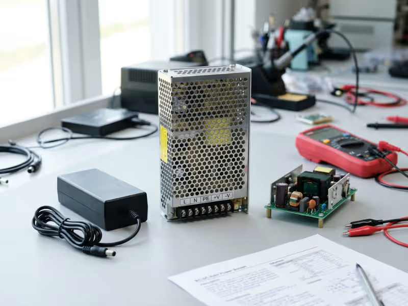
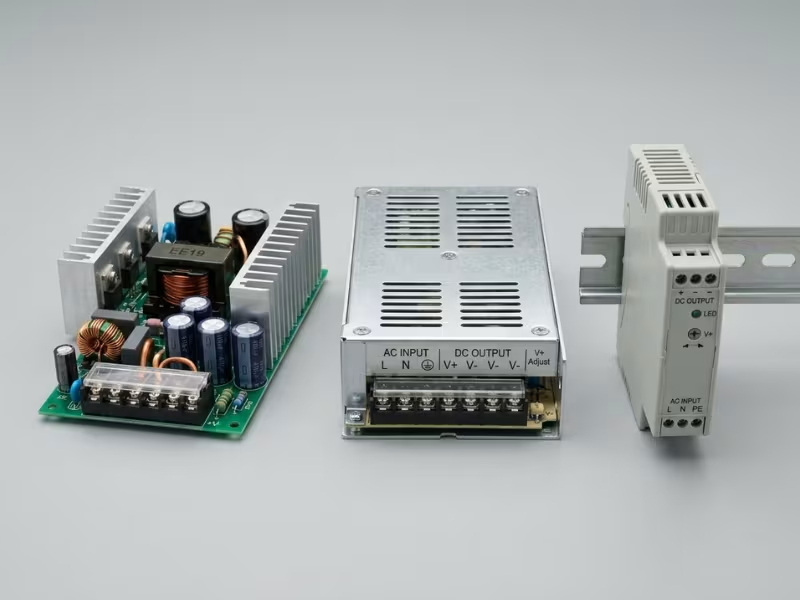
Form Factor | Best For | How It Sheds Heat | Watch Out For |
|---|---|---|---|
Open-frame | Equipment with its own chassis and airflow | Bare components cool into the surrounding air | High ratings often assume 10–20 CFM of forced air |
Enclosed | Industrial equipment, LED systems, test benches | Metal case, vents, sometimes an internal fan | Blocked vents and fan wear |
Encapsulated | Compact, sealed, or high-vibration products | Potting spreads heat to the case and PCB | Needs a thermal path, such as copper or a metal wall |
DIN rail | Control cabinets and automation panels | Vertical convection through the housing | Spacing and mounting direction |
Three installation details change usable power more than most buyers expect:
- Airflow assumptions. An open-frame unit rated 65 W with a fan may deliver only 40–45 W in still air. Read both ratings.
- Orientation. Convection only works when hot air can rise away from the parts. Most open-frame ratings assume horizontal mounting with components facing up. DIN rail units expect vertical mounting. Turn either one on its side, and some suppliers derate output by 20–25%.
- Clearance. DIN rail units often need 10–15 mm on each side and 25–50 mm above and below. Pack them tight, and each unit heats its neighbor.
Two cases show how this plays out.
A kiosk maker used a 65 W open-frame unit in a fanless plastic housing. The load was only 50 W, which looked safe. But the 65 W rating assumed forced air. Inside the box, the electrolytic capacitors ran near 95°C. Units began failing at around 18 months. A 100 W unit at the same price point would have run far cooler.
In another project, a panel builder mounted four DIN rail converters side by side with no gaps. The middle two hit over-temperature protection on summer afternoons. The fix cost nothing: 15 mm spacers and one vent slot.
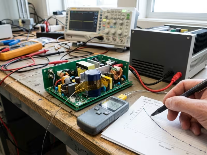
Before you sign off a design, run a simple heat test. Tape a thermocouple to the hottest electrolytic capacitor. Run full load at your highest expected ambient for at least four hours.
Capacitor life roughly halves for every 10°C rise, so I want a 105°C-rated part to stay below about 85°C. If it runs hotter, change the airflow, the mounting, or the converter size before production.
The Specs Buyers and Engineers Misread Most Often
Some specs look simple on a datasheet. You see “PF > 0.95,” “OCP: Yes,” or “MTBF: 500,000 hours,” and you tick the box.
These three specs cause more confusion than any others I review. Each one hides a question that the headline number doesn’t answer. Here’s what to ask instead.
Power Factor: Important for Some Projects, Irrelevant for Others
Power factor tells you how efficiently a converter draws current from the wall. A unit with a low power factor pulls current in short, sharp spikes. That raises the RMS current on the line and adds harmonics to the grid.
A basic converter without power factor correction (PFC) usually sits around 0.5 to 0.65. Active PFC pushes it to 0.95 or higher.
Here’s what that means in practice. Take a 150 W load at 88% efficiency on a 115 VAC line:
- At PF 0.55: about 2.7 A from the wall
- At PF 0.95: about 1.6 A from the wall
One unit won’t matter. Twenty units on one 15 A branch circuit will. The low-PF setup trips the breaker, while the high-PF setup has room to spare.
You likely need active PFC when:
- Your finished product draws more than 75 W and you sell it in the EU, where IEC 61000-3-2 sets harmonic limits
- You build lighting products above 25 W, which face stricter limits
- Many units share one circuit, generator, or UPS
- A customer or utility program sets a minimum PF, often 0.9
You usually don’t need it when:
- Your device draws well under 75 W
- You sell only into markets with no harmonic rules for your product type
- The device runs alone on its own outlet
Remember that harmonic limits apply to your finished product, not to the converter alone. A 100 W converter in a 60 W device may not need PFC.
Don’t pay for active PFC you won’t use. It adds cost, parts, and a little efficiency loss at light load.
Protection Features: The Behavior After a Fault Matters Most
Almost every datasheet lists overvoltage, overcurrent, short-circuit, and over-temperature protection. So buyers compare these as yes-or-no specs. That misses the real question: what does the converter do after it trips?
There are three common behaviors, and each suits a different job:
Fault Behavior | What Happens | Good Fit | Risk |
|---|---|---|---|
Hiccup (auto-recovery) | Shuts off, then retries every few hundred ms | Remote equipment, LED systems, telecom | May fail to start big motor or capacitive loads |
Constant current | Holds current at the limit and lets voltage drop | Battery charging, motor startup | Runs hot if the overload lasts too long |
Latch-off | Stays off until you cycle the AC input | Lasers, heaters, machines that must not restart on their own | Needs a person or controller to reset it |
I choose the behavior from the application, not the datasheet.
A sensor node on a remote pole should recover by itself. Nobody wants a site visit to reset one tripped supply.
A machine with moving parts is different. If a jammed motor trips the converter and it restarts on its own, that motor can lurch while someone clears the jam. Latch-off is the safer choice there.
Watch for mixed behavior too. Many units recover automatically from overcurrent but latch off on overvoltage. Others recover from over-temperature only after they cool down.
Ask the supplier for the exact mode of each protection, plus the trip thresholds. OVP often trips at 115% to 135% of rated output. Check that your load can survive that voltage for a moment.
Then test it. Short the output on the bench, and watch what happens with your real load connected.
MTBF and Lifetime: Two Very Different Numbers
MTBF is the most misread number on any datasheet. A 500,000-hour MTBF does not mean the converter lasts 57 years.
MTBF describes random failure rates across a large group of units during their useful life. It does not predict when parts wear out. With 1,000 units and a 500,000-hour MTBF, you can expect about 17 or 18 random failures each year.
The number also depends on how the supplier calculated it. Telcordia SR-332 often gives a much higher figure than MIL-HDBK-217F for the same design. Most suppliers also calculate at 25°C, and some use light load. Two MTBF figures from two suppliers rarely compare fairly.
So I treat MTBF as background noise. These four signals tell me far more:
- Electrolytic capacitor life. These parts usually wear out first. A 105°C capacitor rated for 5,000 hours lasts about 80,000 hours at 65°C. At 85°C, it lasts only about 20,000 hours. Ask for the capacitor ratings and their measured temperature at full load.
- Lifetime estimate at your conditions. Good suppliers publish a lifetime figure or curve at a stated ambient and load, such as “7 years at 40°C, 75% load.” That number reflects wear-out, not random failure.
- Warranty length. A 5-year warranty shows more confidence than a 2-year one. It also tells you the supplier ran its own lifetime math.
- Vendor support. Ask what happens when a unit fails in the field. A strong supplier offers failure analysis, a written root-cause report, and a clear RMA process.
When a supplier sends only an MTBF figure, ask for the capacitor temperatures and the lifetime estimate. If they can’t provide them, you’ve learned something useful about their testing.
Safety, Isolation, and Certification: What You Actually Need to Verify
Safety specs look settled on a datasheet. You see “reinforced isolation,” a row of logos, and a standard number, and it feels like the work is done.
In practice, this is where I find the biggest gaps between what a supplier claims and what it can prove. You don’t need to learn every standard. You need to confirm three things: the isolation fits your device, the certification fits your application, and the certificate is real.
Isolation Level: Match It to How Your Device Is Built
Isolation keeps mains voltage away from the parts people touch. Most converters use one of two levels.
- Basic isolation gives one layer of protection. It is only safe when a second layer backs it up, usually a protective earth connection. That means a three-prong plug and a grounded metal chassis, which is a Class I design.
- Reinforced isolation gives protection equal to two independent layers. It stays safe without an earth connection, so you need it for Class II products with two-prong plugs and plastic housings.
The test voltage shows the difference. Under IEC 62368-1, basic isolation on a 230 VAC converter typically faces around 1,500 VAC primary-to-earth. Reinforced isolation faces about 3,000 VAC primary-to-secondary.
I start with one question: does the device have a reliable protective earth? If the answer is no, or if a user could plug it into an ungrounded outlet, I only shortlist converters with reinforced isolation from input to output.
Creepage and clearance affect selection in two cases:
- Altitude. Standard ratings assume 2,000 m or lower. A device used in high-altitude cities or mines needs larger clearances, so ask the supplier for its altitude rating.
- Pollution. Dusty or humid sites, such as factory floors or outdoor cabinets, often call for pollution degree 3. That needs wider creepage than a typical office-grade board provides.
If your site is harsh, confirm the rating in the test report, not just the datasheet.
Which Certifications Matter for Your Application
A converter certified to the wrong standard can force a full retest of your product. So I match the standard to the end product first, then check the region.
Application | International / EU | United States | Notes |
|---|---|---|---|
IT, AV, networking, office equipment | IEC/EN 62368-1 | UL 62368-1 | UL 60950-1 is withdrawn, so avoid units certified only to it |
Household appliances | IEC/EN 60335-1 | UL 60335 or UL 1310 (Class 2) | The converter often needs approval within the appliance’s own standard |
Medical devices | IEC/EN 60601-1 | ANSI/AAMI ES60601-1 | Check MOOP/MOPP rating and leakage current |
Lab and test instruments | IEC/EN 61010-1 | UL 61010-1 | Often missed by buyers who default to 62368-1 |
For IT, AV, and networking products, start your search with ITE power supplies that already carry an IEC 62368-1 certificate. That one filter saves a lot of time later.
The US and EU handle approval very differently.
In the US, safety marks come from third parties. A Nationally Recognized Testing Laboratory (NRTL), such as UL, CSA, Intertek (ETL), or TÜV, tests and lists the product.
Also check the mark type. A UL Listed mark covers a standalone product, like an external adapter. A UL Recognized component mark covers a part, like an open-frame board, and comes with conditions of use. Your end product must meet those conditions.
In the EU, CE marking is a self-declaration. The manufacturer signs a Declaration of Conformity under the Low Voltage, EMC, and RoHS directives. No lab has to approve it. That’s why I always ask for the test report behind the CE mark.
For external power supplies, check efficiency rules as well. The US requires DoE Level VI. The EU applies Ecodesign Regulation (EU) 2019/1782.
How to Check Whether a Certification Is Real
A logo printed on a label or datasheet proves nothing. I’ve seen copied UL marks, expired TÜV certificates, and real certificates that cover a different model. Checking takes about ten minutes.
- Ask for the certificate number or file number. A UL file number starts with “E,” such as E123456. A real supplier sends it the same day.
- Search the database yourself. Use UL Product iQ for UL, TÜV Rheinland Certipedia or the TÜV SÜD certificate search for TÜV marks, and the IECEE database for CB certificates. Don’t trust a PDF alone, since anyone can edit one.
- Match the exact model number. Suffixes matter. A certificate for “XYZ-60-12” may not cover “XYZ-60-12-M” with a different connector or enclosure.
- Check the standard and edition. Confirm it matches your application, for example 62368-1 and not an old 60950-1 file.
- Confirm the status and ratings. The certificate should show as active, with input range, output, and ambient ratings that match the datasheet.
- Request the full CB test report. It lists the isolation diagram, test results, and conditions of acceptability, such as required mounting, earthing, or enclosure.
If the model in the database doesn’t match the one on your quote, stop there. Ask the supplier to fix it in writing before you place an order. A converter with a mismatched certificate counts as uncertified, and your test lab will treat it that way.

Off-the-Shelf or Custom? How to Pick the Right Path
Once your specs are clear, the next question is how to buy. You can choose a catalog converter, modify one, or build your own.
I make that decision the same way on every project. I list the gaps between the best catalog unit and the device. The length of that list usually points to the right path.
When Off-the-Shelf Is the Clear Winner
A standard converter makes sense when it meets your needs with margin and your device can work around it. I look for these signs:
- Low volume. You need fewer than about 1,000 units a year.
- Tight schedule. You need samples this week and production in 4 to 8 weeks.
- Standard specs. You use a common rail, such as 12 V or 24 V, and your load sits well inside the derating curve.
- Matching certification. The converter already holds a certificate for your end product’s standard.
The biggest advantage is the existing safety file. Your lab can reuse the CB report instead of testing the converter from scratch.
The Hidden Costs of a “Cheap” Standard Unit
A catalog price only covers the part. Integration adds costs that never appear on the quote. I count these before I decide a standard unit is cheaper:
- Integration labor. Adapter harnesses, crimped pigtails, and custom brackets can add $2 to $5 per unit, plus assembly time.
- Extra filter stages. A converter that passes EMC with only 1 to 2 dB of margin may push your system to fail. The fix is often an added common-mode choke or ferrite. That means more parts, more board space, and another EMC test run.
- Oversizing for heat. A unit that derates in your enclosure may force you up one power class. That step often costs 20 to 40% more.
- Compliance retesting. The converter’s certificate may cover the wrong standard or a different variant. If so, your lab must test it inside your product. That can add weeks and several thousand dollars.
On a 5,000-unit run, $4 of extra parts and labor per unit adds up to $20,000. That figure often exceeds a modification fee.
Modified Standard: The Practical Middle Path
This path fits when a catalog unit covers about 80 to 90% of your needs. Common changes include:
- A different output connector or cable length
- A trimmed output voltage, such as 13.8 V instead of 12 V
- Conformal coating for humid sites
- New mounting holes or a custom label
These changes usually leave the safety-critical parts alone. In that case, the supplier can often update the certificate after a short review.
Expect a modest engineering fee and first lots in 6 to 10 weeks. Minimum orders often start at a few hundred units. Before you approve any change, ask the supplier in writing which parts of the safety report it affects.
When Custom Is Worth the Effort
Custom pays off when workarounds stop solving the problem. These triggers usually push a project toward a custom design:
- Enclosure constraints. The converter must fit a 20 mm-high slot, a curved housing, or a shared PCB.
- A tight thermal path. A sealed box with no airflow may need a converter designed to move heat into a metal wall.
- IP rating. Outdoor or washdown equipment rated IP67 often needs potting and sealed connectors from the start.
- Unique output combinations. One example is 24 V at 5 A, plus an isolated 5 V standby rail and a 3.3 V logic rail.
- Specialized certifications. Few catalog units carry medical, railway, or hazardous-location approvals.
In those cases, custom power adapters often make more sense than forcing a standard converter into a tight enclosure, an awkward connector layout, or a difficult thermal path.
Custom gives you full control, but it takes time and testing. Plan for 4 to 9 months and full safety and EMC testing. To recover the cost, volumes usually need to reach a few thousand units a year.
One warning sign matters most. Your “modification” may change the transformer, the enclosure, and the outputs all at once. If it does, you’re already doing a custom design. Budget and schedule for it that way from the start.
A Practical Selection Checklist
Nine specs are a lot to juggle at once. So I check them in a fixed order. Each step removes some converters, and by the end only a few strong options remain.
Keep your one-page device sheet in front of you as you go. Every step refers back to it.
1. Calculate the real load.
Add up the continuous current on each rail with every feature running. Add 20–30% headroom. Then list every peak, such as motor starts, solenoids, or large capacitor banks, and note how long each one lasts.
2. Confirm the input range.
Match the input to every market you ship to. If you sell in more than one region, start with universal 90–264 VAC. Then check output at low line, because some units derate below 100 VAC.
3. Check thermal fit and derating.
Measure the air temperature around the converter inside your enclosure. Read the derating curve at that temperature. If the usable power no longer covers your load plus headroom, move up one power class now, not after the field returns start.
4. Confirm mounting and enclosure fit.
Match the form factor to the way your device cools. Check the airflow, orientation, and clearance that the rating assumes. An open-frame rating based on 20 CFM of forced air means little inside a fanless box.
5. Verify safety and certification.
Choose the standard that fits your end product: IEC 62368-1, 60335, 61010, or 60601-1. Use reinforced isolation if the device can’t count on a reliable earth. Look up the certificate number in the issuing lab’s database, and match the exact model suffix.
6. Compare protection behavior.
Ask how each protection resets, not just whether it exists. Auto-recovery suits remote equipment. Latch-off suits machines that must not restart on their own. Then short the output on your bench with your real load connected.
7. Assess reliability signals.
Set the MTBF figure aside. Ask for capacitor temperatures at full load, a lifetime estimate at your ambient, the warranty length, and the RMA process. A supplier that can’t share these has told you something important.
8. Shortlist two or three options.
Keep only the converters that pass every step. Order samples of each, and run a four-hour heat test at your highest expected ambient. Compare prices only after that test.
I aim for two or three finalists. With only one, a long lead time or a sudden end-of-life notice leaves you stuck. With more than three, you spend bench time you don’t need to spend.
One last habit pays off later. Write down why each rejected converter failed. That short note saves hours when the next project starts, or when a supplier comes back with a “new and improved” version of the same part.
Common Mistakes That Waste Time and Money
Most converter problems I get called in to fix don’t come from bad parts. They come from good parts chosen for the wrong reasons.
The same five mistakes keep showing up, and each one seems reasonable when someone makes it. Here’s what each mistake looks like in practice and what to do instead.
Assuming More Watts Is Always Safer
Oversizing feels like cheap insurance. It rarely is.
A converter running at 15 to 20% of its rating usually sits at the weak end of its efficiency curve. A 150 W unit driving a 25 W load might run at 80% instead of 90%.
Many designs also switch into burst mode at light load. That can add audible noise and extra output ripple. On top of that, you pay for a bigger case, a higher unit price, and sometimes active PFC you don’t need.
I aim for a continuous load of 70 to 80% of the derated rating. If your load sits below about 40%, a smaller unit usually runs better and costs less.
Trusting Headline Efficiency
“Up to 94%” usually means 230 VAC input, full load, and 25°C air. Your device may run at 115 VAC and 40% load for most of the day. At that operating point, the same converter might deliver only 88%.
Six points sounds small. On a 100 W load, it roughly doubles the heat inside your enclosure. So pull the efficiency-versus-load curve and read it at your real input voltage and load. Run your heat math from that number, not from the brochure.
Ignoring Peak Load and Startup Current
A converter sized for the steady load can still fail every morning. I see this most with motors, pumps, cold heaters, and boards with large bulk capacitors.
One customer powered a 24 V conveyor controller with a 2.5 A unit. The running current was 1.8 A, so the sizing looked safe. But the motor pulled 5 A for about 400 ms at start. The converter dropped into hiccup mode, retried, and tripped again. The line never started.
Before you choose, put a current probe on the load and capture the startup surge on a scope. Note the peak and how long it lasts. Then check both against the converter’s peak rating and maximum capacitive load.
If several units power up together, check their input inrush too. Four converters switching on at once can trip a breaker that handles each one alone.
Treating Any Certification Logo as Proof
A UL or CE mark on a label is only a picture. It doesn’t prove that a lab tested your exact model. It doesn’t prove the certificate is still active. It also doesn’t show that the certificate covers the standard your end product needs.
I’ve rejected parts where the certificate covered the 12 V version but not the 24 V version on the quote. Another unit held only an IEC 60950-1 certificate, which no longer works for new IT products. Both parts looked fine on the datasheet.
Ask for the file number, look it up in the lab’s database yourself, and match the full model suffix. Those ten minutes cost far less than a failed safety review.
Skipping the Derating Curve
This mistake causes more field returns than any other I see. The buyer checks the rated power at 25°C. The converter then lands in a 55°C enclosure and runs past its limit every day for months. Nothing fails at first. Then the capacitors start to dry out.
The derating curve often sits on the last page of the datasheet, so people miss it. Read the notes beside it as well: mounting direction, airflow, and input voltage. If your setup doesn’t match those conditions, treat the curve as optimistic.
Then confirm the result on your bench. Run a four-hour, full-load test at your hottest expected ambient, with a thermocouple on the main electrolytic capacitor. That test tells you more than any datasheet can.
None of these mistakes costs much to avoid. Each one takes an hour or less to catch at the selection stage. Once the product ships, each one can cost weeks of rework, a redesign, or a full batch of field returns.
FAQs
What size AC-DC converter do I need for my device?
Start with your continuous load, not the converter catalog. Add up the real current on each rail with every feature running. Then add 20–30% headroom so the converter runs at about 70–80% of its rating.
For example, a 12 V device that draws 3 A uses 36 W. With headroom, you need about 45–48 W, so a 12 V, 4 A unit fits.
Size depends on more than watts:
- Peak load. Can the unit carry startup surges long enough?
- Derating. Does it still deliver 48 W at the air temperature inside your enclosure?
If either answer is no, move up one power class.
Can I use a converter with a higher voltage rating than my device requires?
It depends on which rating you mean.
Output voltage must match. A 19 V converter on a 12 V device can damage it within seconds. A small trim of a few percent is fine. Some devices also accept a wide input, such as 9–36 V, because they have their own regulator. Check the device spec before you rely on that.
Higher current ratings are safe. A 12 V, 5 A converter on a 2 A device works fine. The device only draws the current it needs.
A wider input range is also fine. Before you plug anything in, confirm the polarity and connector as well.
What does universal input mean on a converter?
Universal input means the converter accepts any common mains voltage without a switch. The usual range is 90–264 VAC or 85–264 VAC, at 47–63 Hz. That covers 100 V in Japan, 120 V in North America, and 230 V in Europe and most of Asia.
For products sold in more than one region, I choose universal input by default. You get one part number for every market.
Check two details behind the headline range:
- Low-line output. Many units derate below 100 VAC.
- Brownout behavior. A good unit shuts down cleanly and restarts on its own when the voltage recovers.
How do I calculate the wattage my device needs?
Multiply voltage by current on each output rail, then add the rails together. For example:
- 24 V × 1.5 A = 36 W
- 5 V × 2 A = 10 W
- Total: 46 W
Add 25% headroom, and you need about 58 W, so a 60 W converter fits.
Measure the current instead of trusting the nameplate. Use a DC clamp meter or an inline meter, and run the device with every feature on. Then capture the startup surge on a scope. Motors, heaters, and large capacitors can pull two to three times their running current for a few hundred milliseconds.
What is the difference between an AC-DC adapter and an AC-DC module?
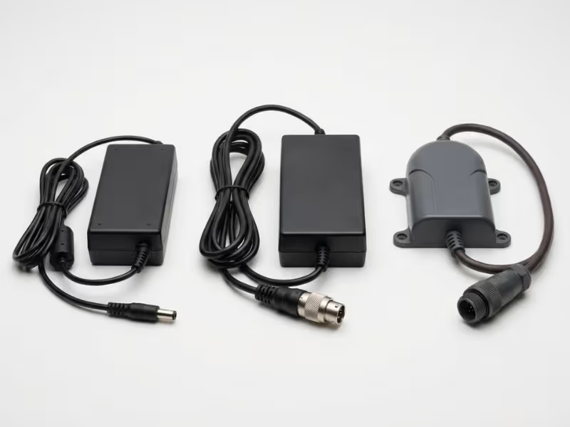
An adapter is an external, standalone unit. It can be a wall-plug or desktop design with its own case and cords. It usually carries a UL Listed mark, and it must meet efficiency rules such as DoE Level VI. Because it keeps mains voltage outside your product, it can simplify your own safety approval.
A module mounts inside your equipment. Common types include open-frame, enclosed, PCB-mount, encapsulated, and DIN rail units. Modules usually carry a UL Recognized mark with conditions of use, so your enclosure must provide cooling and fire protection.
Choose an adapter for speed and simpler approval. Choose a module for a clean, integrated design.
Why does my converter get hot, and is that normal?
Some heat is normal. Every watt the converter loses turns into heat. A 60 W load at 90% efficiency creates about 6.7 W of heat. Case temperatures of 40–60°C are common at full load.
Treat these signs as warnings:
- The case is too hot to hold for a few seconds
- You notice a burning smell, discoloration, or buzzing
- The output keeps cutting out and restarting
The usual causes are overload, blocked vents, the wrong mounting direction, or high ambient air. Measure the load first. Then check the airflow and clearance around the unit.
What certifications does an AC-DC converter need in the US and EU?
The right standard depends on your end product. For IT and general electronics, these are the main requirements.
United States:
- An NRTL safety listing to UL 62368-1, from a lab such as UL, CSA, or Intertek
- FCC Part 15 for EMC
- DoE Level VI efficiency for external power supplies
European Union:
- CE marking backed by a Declaration of Conformity
- The Low Voltage Directive, using EN 62368-1
- The EMC Directive
- RoHS
- Ecodesign Regulation (EU) 2019/1782 for external power supplies
Household, lab, and medical products need IEC 60335, IEC 61010, or IEC 60601-1 instead. Always confirm the exact model number in the lab’s online database.
What is derating, and why does temperature matter?
Derating means the converter delivers less power as conditions get harsher, mainly as the surrounding air gets hotter. A typical curve holds 100% output up to 50°C. Then it drops to about 50% at 70°C.
Heat matters because components age faster when they run hot. Electrolytic capacitor life roughly halves for every 10°C rise.
Here’s how it works in practice. A 60 W unit on the curve above delivers only about 45 W at 60°C. If your load is 48 W, that unit won’t hold up.
Measure the air around the converter inside your enclosure. Then read the curve at that temperature before you order.
Conclusion
Nine specs can make converter selection feel like a long spreadsheet exercise. It doesn’t have to. These specs don’t carry equal weight, and treating them that way slows you down.
Three questions decide most outcomes. Can the converter carry your real load, including peaks? Can it still do that at the air temperature inside your enclosure? Does it hold a valid certificate for your end product’s standard? If any answer is no, power factor, MTBF, and size won’t rescue it.
That’s why I confirm load, thermal derating, and certification before I look at a single price. A cheap unit that derates in your box or fails your safety review costs far more later.
Start with your one-page device sheet. Run each candidate through those three checks, and cut every converter that misses even one. Then order samples of the two or three that remain, and let a bench heat test make the final call.