Most OEM power supply problems don’t start with a bad supply. They start with a wrong spec early in the project.
Rated wattage is only the starting point. Derating, the real environment, EMC, certifications, and system integration decide whether a supply works in the field.
I have helped many OEM teams choose power for new products. Most of the redesigns I see start when teams match the wattage and move on. This guide shows you how to make each choice in the right order, so you avoid field failures and costly rework when comparing different AC-DC power products for OEM equipment.
Why AC-DC Power Supply Selection Fails So Often
A power supply is often one of the cheapest major parts on the BOM. A 150 W open-frame unit may cost $15 to $30 in volume. That low price tempts teams to treat it like a commodity: match the voltage, match the wattage, and move on.
The real cost shows up later, and it rarely stays small. A wrong supply can lead to:
- Field failures that look like random resets or software bugs
- EMC failures that force a new filter, a new layout, or a shielded enclosure
- Thermal shutdowns in hot cabinets or sealed housings
- Warranty claims and site visits that cost more than the supply itself
- Redesigns that reopen safety and EMC testing
Most of these problems share one root cause. The wattage matched, but the supply didn’t fit.
A datasheet headline describes a best case. It usually assumes 25°C ambient, nominal input voltage, free air, and a set mounting position. Your product rarely runs in those conditions. Once heat, airflow, and line voltage shift, the usable power can drop well below the number on the label.
Here’s a case I see in different forms every year.
A team built an industrial controller for outdoor cabinets. Peak load reached about 95 W. They chose a 120 W supply, which gave them roughly 25% headroom. In the lab, at 25°C and 230 VAC, it ran perfectly. Every test passed.
Then summer arrived. The cabinets sat in direct sun, and internal air reached 55°C. The supply delivered full power only up to 40°C, then derated to 50% at 70°C. At 55°C, it could safely deliver about 90 W.
Some sites added a second problem. Long cable runs pulled the input down near 90 VAC, and the supply lost another 10% below 100 VAC. Usable power fell to roughly 80 W. Each time a relay and a cooling fan started together, the supply hit its overtemperature limit and restarted.
Field technicians blamed the firmware at first. When the team found the real cause, a larger supply wouldn’t fit the enclosure. They redesigned the mounting plate, reran EMC, and replaced units already in service. They lost most of a season.
The supply wasn’t defective. The spec was. That’s why I never start with wattage. I start with how hot it gets, what the input looks like, and how the load behaves at its worst moment.
Start With the Real Load, Not the Nameplate
When a team tells me, “We need a 100 W supply,” I always ask the same question back: 100 W when? At idle? At full run? In the half-second when everything switches on at once?
A nameplate number tells you what the parts draw on average. It says nothing about the moments that actually trip a supply. So before I open a single datasheet, I map the load in three passes.
Peaks Decide the Size, Not the Average
Most OEM equipment has a calm average and a few sharp spikes. The spikes cause the field failures. These loads create them most often:
- DC motors, pumps, and fans. Startup current often runs 3 to 6 times the running current for 100 to 500 ms.
- PTC heaters. They can draw 2 to 3 times their rated current when cold.
- Radios. A cellular modem may average 0.3 A but pull 2 A bursts during transmit.
- Relays and solenoids. Pull-in current runs well above hold current.
- Displays and downstream boards. Backlights and bulk capacitors pull a surge at power-on.
For each peak, record four things: how high it goes, how long it lasts, how often it repeats, and what else runs at the same time.
That last point matters most. I worked on a label printer that averaged 60 W. When the stepper motor and print head heater started together, it pulled 110 W for about 300 ms. The team had picked an 80 W supply. Its overcurrent protection reacted in milliseconds, dropped into hiccup mode, and the printer rebooted mid-job.
Some supplies carry a peak rating, such as 150% for 10 seconds. Others carry none. If your peak lasts longer than the supply’s rated window, treat it as continuous load.
Check Every Rail on Its Own
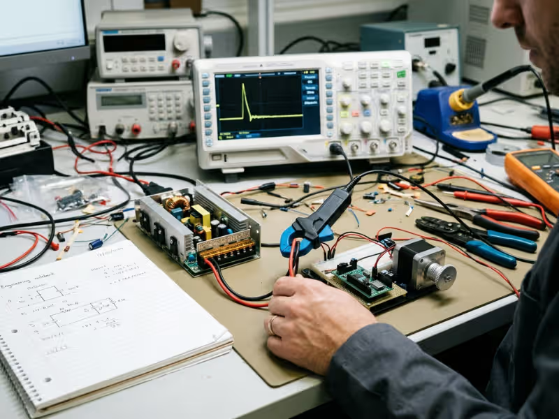
On a multi-output supply, total wattage can hide a problem. A 100 W triple-output unit might limit the 5 V rail to 4 A. Your design can stay under 100 W in total and still overload that one rail.
Cross-regulation causes a quieter problem. Many multi-output supplies tightly regulate only the main rail. The other rails follow it loosely. If the main 5 V rail runs light, say during sleep mode, an auxiliary 12 V rail can drift up to 13 V or more. Many supplies also need a minimum load on the main rail, often 5 to 10%, to stay in spec.
So check the cross-regulation table, not just the rail ratings. Test your lightest real operating state, not only full load. If the numbers look tight, a dummy preload can help. Often, a single regulated output feeding local DC-DC converters works out cleaner.
How Much Headroom Is Enough?
My usual starting margin is 20 to 30% above the worst-case continuous load. Apply that margin to the derated rating at your real ambient temperature and input voltage, not to the headline number.
Go to 40 to 50% when:
- The product runs hot, sealed, or near the top of the derating curve
- Peaks last long or repeat often
- Firmware updates or add-on modules may raise the load later
- Downtime costs far more than a larger supply
Oversizing has its own cost. A 300 W supply running at 15% load may hit only 80% efficiency, while a right-sized unit near 50% load can exceed 90%. Oversized supplies also draw more at no load, take more board space, cost more, and create higher inrush current.
I aim for continuous load at 50 to 80% of the derated rating. That range keeps the supply efficient, cool, and ready for real peaks.
Put the whole load curve on one page: peaks, durations, and per-rail currents. That page sizes the supply far better than any wattage label.
The Three Conditions That Usually Eliminate the Wrong Supply Fast
Once you know your real load, you’ll likely face a long list of supplies that look right on paper. I don’t compare them one by one at this stage. I run three quick filters first. Together, they usually cut a list of twenty candidates down to three or four.
Apply them in this order. Each one removes options the next filter never needs to see.
Filter 1: Can It Handle Your Real Input?
Start with where the product ships. North America runs on 120 VAC, Japan on 100 VAC, and most of Europe and Asia on 230 VAC. A universal input of 90–264 VAC covers all of them with one part number. For most OEM products, I treat universal input as the default.
Switch-selectable 115/230 VAC supplies still appear in some higher-power and legacy designs. They carry a real risk. One installer sets the switch wrong, and the unit fails on day one. If you sell globally, drop them.
Next, look below the nominal range. Rural grids, generators, and long cable runs can sag toward 90 VAC or lower. Many supplies derate by 10 to 20% under 100 VAC. Check the input derating curve, not just the input range.
Finally, glance at inrush current. Some supplies pull 40 to 60 A for a few milliseconds at cold start. That spike can trip upstream breakers. Also note the surge rating, since industrial and outdoor sites often need more than the basic level.
Filter 2: Does It Survive Your Real Thermal Setup?
Most datasheet ratings assume free-air convection at 25°C, in one mounting position. Your supply will probably sit inside an enclosure, where air runs 10 to 20°C warmer than the room.
So measure, or at least estimate, the air right around the supply. Then ask three questions:
- Free air or enclosed? A sealed box removes most convection cooling.
- Convection or forced air? A forced-air rating only applies if your fan delivers the stated airflow, often 10 to 20 CFM. If the fan fails, the supply falls back to its convection rating.
- What altitude? Above 2,000 m, thinner air cools less and arcs more easily. Many supplies need extra derating or wider clearances there.
If a supply can’t deliver your load at your real internal ambient, cross it off now.
Filter 3: Which Safety Path Is Your Product On?
You don’t need to master every standard. You just need to know which family your end product falls under, because that decides which supplies you can even consider.
- IEC 62368-1 covers IT, office, and audio-video equipment. Most general OEM supplies certify here.
- IEC 60601-1 covers medical electrical equipment. It requires much tighter leakage and isolation, so most commercial supplies fall out immediately.
- IEC 61010-1 covers test, measurement, and lab equipment. Labs often accept 62368-1 supplies here, but check overvoltage category and pollution degree first.
If you’re unsure, ask your test lab one question: “Which standard will you evaluate our product against?” That answer alone can remove half your list.
Run these three filters before you request samples. You’ll spend your test time on supplies that can actually work.
Choose the Right Power Supply Form Factor and Architecture
Form factor looks like a mechanical detail. It actually decides three things: who owns safety at the system level, how the supply stays cool, and what happens when a unit fails in the field. I settle it right after the three filters, before I compare part numbers.
The table below gives you the quick view. The choices behind it follow.
Supply Type | Best For | Main Advantage | Main Tradeoff |
|---|---|---|---|
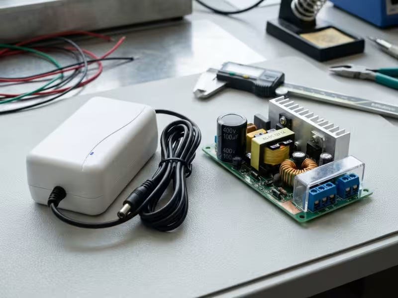
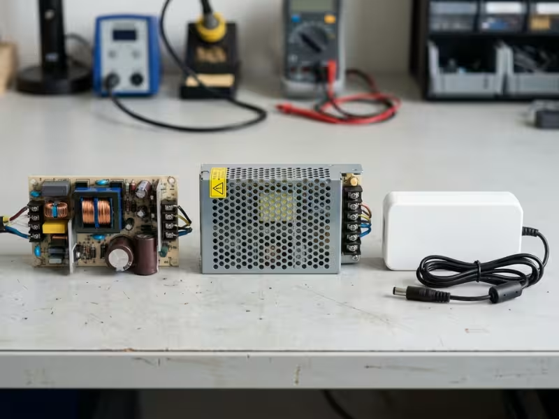
Open frame | High-volume products with a closed OEM enclosure | Lowest cost per watt, smallest footprint | You own touch safety, spacing, and airflow |
Enclosed (U-channel or metal case) | Industrial panels, cabinets, higher power | Built-in protection, easy mounting | Larger and heavier, often fan-cooled above 300 W |
External adapter | Desktop, portable, and home devices | Keeps AC mains and heat outside the product | Cable damage, lost adapters, wrong-plug risk |
Single output + local DC-DC | Products with several low-power rails | Tight regulation right at each load | Extra board space and parts |
Modular or redundant (N+1) | Downtime-critical systems | Hot-swap service, no single point of failure | Higher cost, size, and complexity |
Open Frame, Enclosed, or External Adapter?
An open-frame supply costs the least because it leaves the hard work to you. Its primary side sits exposed. Your enclosure must keep fingers and tools away from live parts and hold creepage to nearby metal. It must also move enough air across the board. Open frame works well when you control a closed housing and build in volume, such as test instruments, kiosks, or printers.
An enclosed supply brings its own cover and terminal block. It already handles touch safety, so you mainly manage mounting and airflow. It suits industrial cabinets where an electrician wires it in. Above roughly 300 W, most enclosed units add a fan. Plan for fan life and dust from day one.
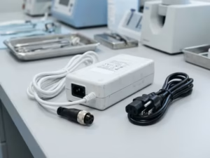
An external adapter moves mains voltage and most of the heat out of your product. Your device sees only low-voltage DC, which often simplifies its own safety approval and shrinks the enclosure. Service gets easy, too. A customer swaps the adapter, not the device.
The weak point is the cable. Users bend it, lose the adapter, or grab the wrong one from a drawer. If a wrong voltage could damage your product, use a keyed or uncommon DC connector. This is also where many teams start looking at custom power adapter options instead of forcing a standard adapter into the wrong use case.
One Output, Many Outputs, or One Rail Plus DC-DC?
Once the format is clear, decide how many rails the supply itself should deliver.
A single output is the simplest choice when one voltage feeds most of the load, such as 24 V for motors and valves. A multi-output supply looks tempting when you need 5 V, 12 V, and 24 V. On paper, it saves parts. In practice, the auxiliary rails often regulate loosely and depend on a minimum load on the main rail.
My rule is simple. If one rail carries more than about 70% of the power, choose a single output at that voltage. Then place small DC-DC converters next to each low-power load.
A 24 V main rail with a 5 V buck on the logic board gives you three wins. You get tight regulation right at the chip and cleaner grounding. You can also change one board without requalifying the whole supply.
Multi-output still makes sense in high-volume products with stable, balanced rails, where every cent on the BOM counts.
When Modular or Redundant Designs Earn Their Cost
Most products don’t need redundancy. A few can’t run without it.
I ask one question: what does one hour of downtime cost? For a telecom shelf, a lab analyzer mid-batch, or a production line controller, that hour can cost far more than a second supply.
That’s where N+1 pays off. Say a 600 W load runs on three 300 W modules. Any two can carry the full load, so one can fail without a shutdown. Add ORing diodes or ideal-diode controllers so a failed module can’t pull the bus down. Make each module report its status, so someone knows to replace it.
The service model matters just as much. Hot-swap modules only help if a technician can reach them and keep a spare on hand. At a remote site with a two-day service window, redundancy buys you those two days. If nobody ever replaces the failed module, you’ve only delayed the outage.
Modular configurable supplies help in another way. You can mix outputs from one chassis across a product family. That lets you qualify one platform instead of five custom supplies.
Match the format and architecture to how your product gets built, cooled, and serviced. The cheapest unit on the quote rarely stays the cheapest one in the field.
Derating, EMC, and Heat: Where “Looks Good on Paper” Breaks Down
A supply can pass every filter and still fail in your product. On a quiet bench, the datasheet looks honest. Inside a warm, crowded enclosure, the same unit behaves like a smaller, noisier, shorter-lived part.
Three problems cause most of these surprises. Each one hides behind a number that looks fine on its own.
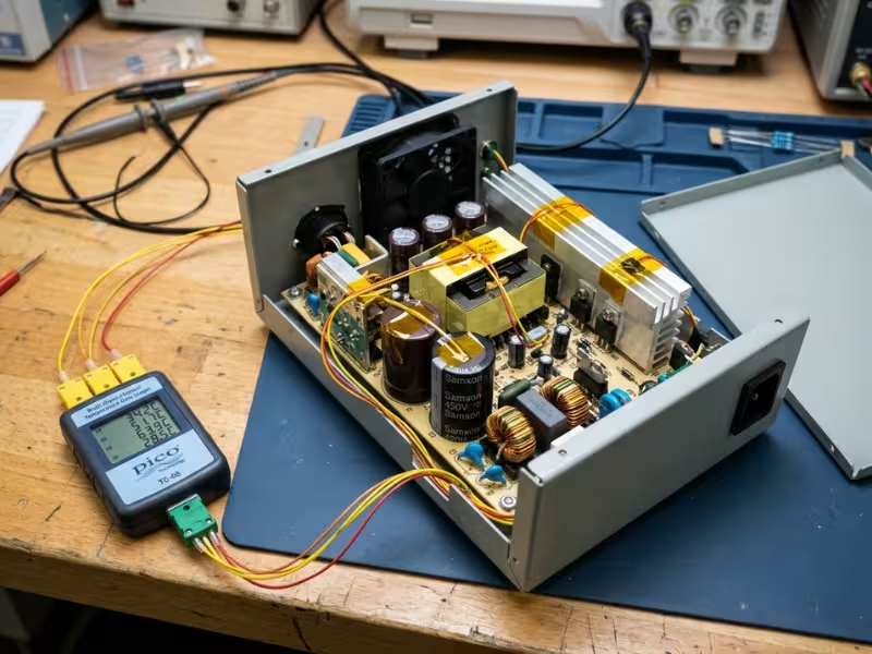
Read the Derating Curve, Not the Headline Wattage
The headline rating usually assumes 25°C ambient, a set mounting position, and sometimes a fan you may not have. Your product almost never matches all three.
Take a common open-frame supply sold as “150 W.” Read the fine print, and you’ll often find:
- 150 W only with 15 CFM of forced air
- 100 W in free-air convection
- Full power up to 50°C, then a drop to 50% at 70°C
Now put it in a sealed instrument with no fan, where the air around the board reaches 60°C. Convection gives you 100 W. At 60°C, the curve allows about 75%. Your “150 W” supply now delivers about 75 W.
Mounting position cuts it further. Many supplies assume the components face up so heat can rise off the board. Mount the supply on its side or upside down, and some vendors add another 10 to 20% derating. Others never test it at all.
So I always ask suppliers three questions. What ambient did you rate this at? Which orientation? How much airflow, measured where? If they can’t answer, treat the headline number as marketing.
Build EMC Margin Before the Lab Does It for You
EMC works the same way. The supply’s test report shows how it performed alone, on a test table, with a short cable and a resistive load. Your product adds motors, processors, long harnesses, and its own switching regulators.
Start with the filter. Some open-frame supplies meet Class B emissions only with an added external filter or a grounded metal plate underneath them. Others meet only Class A. Check the test setup in the report, not just the class it claims.
Cables cause the next surprise. A DC output lead of 1 to 2 m can act as an antenna in the 30 to 100 MHz range. The same supply that passed with a 0.3 m lead can fail radiated emissions once you route it past a motor driver. A clip-on ferrite or a shorter route often fixes it. A new layout costs far more.
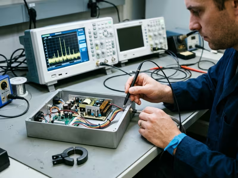
That’s why I push every team toward a pre-scan. A day with a near-field probe and a spectrum analyzer, using the real enclosure and cables, costs very little. I look for at least 6 dB of margin below the limit. A formal test failure means a fix, a respin, and weeks of waiting for a new lab slot.
Efficiency Is a Heat Problem, Not Just an Energy Problem
Most teams read efficiency as a power bill figure. I read it as a heat figure, because every lost watt stays inside your box.
At 100 W output:
- 88% efficiency means about 13.6 W of heat
- 93% efficiency means about 7.5 W of heat
In a sealed enclosure, those 6 extra watts can lift internal air by several degrees. Hotter air pushes you further down the derating curve. It also raises surface temperature, which matters for anything a user touches.
Heat also sets lifetime. Electrolytic capacitors roughly double their life for every 10°C drop. A 105°C, 5,000-hour capacitor running at 65°C may last around 80,000 hours. At 75°C, that falls to about 40,000. Ask your supplier for calculated capacitor life at your real internal temperature, not at 25°C.
For always-on products, watch standby draw too. External adapters must meet DoE Level VI no-load limits, about 0.1 to 0.21 W depending on power. Even when no rule applies, low no-load draw keeps idle heat down and supply life up.
Test the supply under your real conditions. Those are the only numbers that count.
Compliance and Certification: What You Actually Need to Check
A certified power supply feels like a shortcut to a certified product. It isn’t. The certificate proves the supply passed under a specific set of conditions. Your product still has to earn its own approval.
By now, you know your standard family. IEC 62368-1 covers IT and AV gear, IEC 60601-1 covers medical equipment, and IEC 61010-1 covers test and measurement. The next job is to confirm that the supply’s paperwork supports that path in your actual design.
A Recognized Component Is Not an Approved Product
Most OEM supplies carry UL or CSA component recognition. That means a lab evaluated the supply as a part that goes inside something else. It does not mean the lab approved your product.
The real value sits in the test report’s conditions of acceptability. These are the rules you must follow to keep that recognition valid. Typical examples include:
- Install it inside a suitable end-product enclosure.
- Keep ambient temperature below the rated limit.
- Use only the approved mounting orientation.
- Make the required earth connection.
Break one condition, and the approval no longer covers you. I always ask for the full CB report, not just the certificate, and I read that section first.
Match Isolation Ratings to Your Real Setup
Creepage, clearance, and isolation ratings tell you what the supply can safely sit next to. I check three things:
- Insulation grade. If users can touch the output, you need reinforced insulation from input to output.
- Rated conditions. Most supplies assume pollution degree 2, overvoltage category II, and altitude up to 2,000 m. A dusty factory floor or a mountain site may fall outside that envelope.
- Application fit. A reinforced 62368-1 rating does not equal 2 MOPP for medical use.
Your layout can also undo good spacing. A supply with 4 mm of creepage loses it if you mount a metal bracket 2 mm from the primary side.
EMC: The Supply Passed, but Your Product Hasn’t Yet
For emissions, most commercial and residential products need Class B. Use Class A only for industrial equipment where the standard allows it.
For immunity, focus on surge (IEC 61000-4-5) and EFT/burst (IEC 61000-4-4) on the AC port. Industrial standards typically call for 2 kV EFT on power ports, which is double the common residential level. In the EU, products that draw more than 75 W of input power also need to meet harmonic limits, which usually means you need active PFC.
What the PSU Certificate Won’t Solve for You
This is where many OEM teams get caught. The supply’s approval does not cover:
- System leakage current. Leakage from the supply adds to leakage from your own filters.
- Final EMC results. Your motors, cables, and processors create new noise.
- Thermal compliance. The temperatures inside your enclosure are your responsibility.
- Product-level requirements. Fire enclosure, touch protection, markings, and user instructions are all on you.
- Future changes. If you modify the supply, or your vendor swaps a critical part, the approval may lapse.
Draw the line clearly. Your supplier owns the supply within its stated conditions. You own everything outside them. Treat the certificate as evidence for your safety file, not as a pass for your product.
Supplier Questions That Save Trouble Later
Most teams stop asking questions once the samples pass. That’s when I start asking the ones that matter in year three. A supply can pass every bench test and still hurt you through a long lead time, a silent part swap, or a “compatible” replacement that behaves differently.
I group these questions into four conversations. Have each one before you lock the design, not after the first production order.
Lead Time, MOQ, and How Long the Part Will Exist
Ask for lead times at three stages: samples, pilot builds, and full production. A supplier may ship samples in two weeks and still need 12 to 16 weeks for production volume. Your launch plan has to follow the longer number.
Then ask what drives MOQ. A catalog part may ship in small quantities. A custom label, connector, cable length, or conformal coating can push MOQ to 500 or 1,000 units. Find out which changes trigger a higher MOQ, so a small tweak doesn’t lock you into a large order.
Finally, ask about lifecycle. How long do they plan to build this model? How much notice do they give before end of life? I look for at least 6 to 12 months of last-time-buy notice. If your product sells for seven years, a supply with a two-year horizon becomes your problem.
Change Notification: The Clause That Protects Your Certification
Your safety file names a specific supply. Your test lab evaluated that exact build. If the vendor changes the transformer, a Y-capacitor, an optocoupler, or the fuse, your approval may no longer cover the product you ship.
I’ve seen this go wrong quietly. One vendor switched to a different insulation tape on the transformer to fix a sourcing problem. Nobody told the OEM. The change showed up during a factory audit, and the team had to prove the new build still met its spacing and leakage limits.
So ask for a written change-notification policy and check four points:
- Which changes trigger notice. Critical safety parts, layout, and manufacturing site should all count.
- How much notice. I ask for at least 90 days.
- What you receive. You need samples of the changed build and an updated CB report.
- Where it lives. Put it in the supply agreement, not in a sales email.
Design Support and Real Test Data
Good suppliers save you weeks of engineering time. Ask for 3D STEP models, recommended layouts for any external filter, and application notes on grounding and mounting. Also ask for derating curves at more than one orientation.
Then ask about test data. Request the full design verification report, not a one-page summary. It should show thermal results, hold-up time, inrush, and EMC setup details.
Ask how they test production units, too:
- Burn-in. What load, temperature, and duration? Four to eight hours at full load and raised ambient catches many early failures.
- ATE coverage. Does every unit get tested for output voltage, ripple, hipot, and protection trips?
- Traceability. Can they pull test data by serial number if a field unit fails?
If a supplier can’t explain its burn-in conditions clearly, treat that as a warning. If possible, review the supplier’s production and testing facilities as well.

Second Sourcing: “Drop-In” Rarely Means Drop-In
Every purchasing team wants a second source. I support that, but most “drop-in replacements” only match the headline specs. Same voltage, same wattage, and same footprint don’t make two supplies interchangeable.
Before you call an alternative drop-in, compare:
- Pinout, mounting holes, height, and component keep-outs
- Derating curve at your real ambient and orientation
- Inrush current, hold-up time, and minimum load requirements
- Earth connection points and leakage current
- EMC behavior with your real cables and enclosure
- Conditions of acceptability in its safety report
Any one of these can fail your product. A replacement with higher inrush can trip your breaker. One with a different earth point can change your EMC results.
Your safety file also has to list the alternate by name. The lab may need to review it, and you’ll likely rerun EMC pre-scans.
My advice is simple. Qualify the second source during development, alongside the first. Don’t wait until your main supplier announces end of life. At that point, you’re qualifying under pressure, with no time left.
Ask these questions early, and get the answers in writing. A slightly higher unit price from a supplier with solid change control often costs far less than a cheaper part that surprises you later.
Where OEM Power Supply Selection Usually Goes Wrong
Most power supply failures I review don’t come from a weak product or a careless engineer. They come from a reasonable shortcut taken under deadline pressure. The same five show up across industrial controls, instruments, kiosks, and medical carts. Each one tends to surface late, when fixes cost the most.
Mistake 1: Treating Wattage as the Whole Spec
A team totals the load, gets 180 W, and orders a 240 W supply. The math looks safe. The trouble is that wattage answers only one question. It says nothing about hold-up time during a line dip, regulation on the auxiliary rails, or how the supply behaves next to a noisy motor driver.
The result is a product that resets during brownouts or fails conducted emissions by 4 dB. The team then adds parts to a supply that never fit the job. Treat wattage as an entry filter, not a decision. Before you approve a part, confirm hold-up time, per-rail regulation at your lightest load, and EMC behavior with your real cables.
Mistake 2: Qualifying the Supply After the Layout Is Locked
This one causes the biggest schedule losses. The team picks a supply from the datasheet, finishes the enclosure and board, then runs thermal and EMC tests a few weeks before launch.
That’s when they learn the supply runs 12°C hotter than expected in the sealed housing, or that radiated emissions fail around 60 MHz. By then, a larger supply won’t fit, and a vent or shield means new tooling. I’ve watched a $20 part delay a launch by three months.
Test early instead. Put a sample supply in a rough prototype enclosure with real loads and real cables, and run a thermal check and an EMC pre-scan. Do it while the enclosure is still foam board or a 3D print.
Mistake 3: Believing the Headline Number Applies to Your Box
A supply sold as “200 W” may deliver that only with 20 CFM of airflow, components facing up, and 25°C ambient. Your product may have no fan, a side-mounted board, and 55°C air inside.
Teams rarely see this on the bench, because a lab bench gives the supply ideal conditions. They see it in the field, as thermal shutdowns on hot afternoons or capacitor failures after 18 months instead of seven years.
Pull the derating curve and apply three corrections: your measured internal ambient, your real airflow, and your mounting orientation. Then apply your headroom margin to that derated figure. If the supplier won’t say which orientation they tested, assume the worst.
Mistake 4: Forgetting Inrush When Supplies Share a Breaker
One supply on its own may pull 40 A for a few milliseconds at cold start. That rarely causes trouble. Now put four of them in a cabinet on one 10 A B-curve breaker. They all start at the same instant, the combined surge passes 150 A, and the breaker trips magnetically every time someone powers up the line.
Hot restarts make it worse. Many supplies limit inrush with an NTC thermistor. After a brief outage, the thermistor is still warm, so it limits almost nothing, and the second power-up pulls more current than the first.
Check inrush at both cold start and hot restart. If several supplies share a circuit, choose units with active inrush limiting, stagger their start-up, or specify a C- or D-curve breaker. Agree on this with whoever designs the panel.
Mistake 5: Buying the Wrong Certification Grade
This mistake runs in both directions.
Some teams over-specify. They put a 2 MOPP medical supply into an office printer because it “feels safer.” They pay 30 to 50% more per unit, accept a larger footprint, and narrow their supplier list. They also inherit tight leakage limits that make EMC filtering harder, all for protection their product doesn’t need.
Other teams under-specify. They drop a standard IEC 62368-1 supply into a device that later moves onto a patient cart or into a lab system under IEC 61010-1. The test lab rejects the supply, and the team must requalify a new one late in the project.
Ask your test lab which standard covers your end product before you shortlist anything. Then buy the grade that standard requires, plus any market you realistically expect within the product’s life. More certification than you need doesn’t add safety. It adds cost, size, and design limits.
All five mistakes come from the same habit: judging the supply on paper instead of inside the product, on the circuit, and against the standard it will actually face.
A Practical Selection Workflow
Knowing the pitfalls helps. A repeatable process helps more. When an OEM team asks me where to start, I give them the same five steps and ask them to finish each one before they move on.
The order matters. Each step narrows the field for the next one, so you test fewer parts and test them under the right conditions.
Step 1: Map the Load Before You Open a Datasheet
List every load in the product. For each one, record its continuous draw, its peak, how long that peak lasts, and what else runs at the same moment. Watch motor starts, cold heaters, radio bursts, and power-on surges most closely.
Then split the total by rail. Note the current on each voltage, including your lightest real operating state, such as sleep mode. Add 20 to 30% headroom to the worst-case continuous load. Use 40 to 50% if the product runs hot or may grow later.
Your output: A one-page load profile with per-rail currents, peak size and duration, and a target rating.
Step 2: Write Down the Real Operating Conditions
Now describe where the supply will actually live. Measure or estimate the air right around it, not the room temperature. A sealed box often runs 10 to 20°C warmer than the room.
Record four facts:
- Worst-case internal ambient
- Airflow: free convection, or forced air with a known CFM at the supply
- Mounting orientation
- Maximum altitude, especially above 2,000 m
Add your input voltage range and the lowest line voltage you expect in the field.
Your output: An environment sheet that lets any supplier read the derating curve for your exact case.
Step 3: Confirm the Safety and EMC Path
Ask your test lab which standard covers the end product: IEC 62368-1, IEC 60601-1, or IEC 61010-1. That answer decides which supplies you can even consider.
Next, set your EMC targets. Most commercial products need Class B emissions. Industrial products may use Class A where the standard allows it. Note the surge and EFT levels for your market. If input power exceeds 75 W and you sell in the EU, plan for harmonic limits and active PFC.
Then list what a recognized component approval will cover in your design, and what it won’t.
Your output: A short compliance brief that lists the standard, emissions class, immunity levels, and harmonic needs.
Step 4: Pick the Architecture, Then Shortlist Two or Three Parts
With load, environment, and standard fixed, choose the form factor. Use open frame inside a closed OEM enclosure, enclosed units in cabinets, and external adapters for desktop or home devices.
Decide on rails next. If one voltage carries most of the power, use a single output with local DC-DC converters. Choose multi-output only when the rails stay stable and balanced.
Run each candidate against Steps 1 to 3 and keep two or three. Order samples of each. If you test only one part, you have no fallback when it fails.
Your output: A shortlist of two or three supplies, with derated output at your conditions and samples on order.
Step 5: Test in the Real Box and Question the Supplier
Install each sample in a rough prototype enclosure with real loads and real cables. Run a thermal check at worst-case ambient and full load. Log capacitor and hot-spot temperatures, then compare them with the supplier’s limits.
Next, run an EMC pre-scan and aim for at least 6 dB of margin below the limit. Check inrush at both cold start and hot restart. Confirm hold-up time with your real load attached.
Finally, review the supplier. Ask for the full CB report, written change-notification terms, production lead time, and lifecycle plans.
Your output: Thermal data, a pre-scan report with margin, and written supplier answers for each candidate.
When you finish, you hold five short documents. Together, they turn supply selection from a guess into a decision you can defend at design review. They also give every supplier the same clear brief, so you can compare quotes fairly.
FAQs About Choosing an AC-DC Power Supply
OEM teams ask me these questions on almost every new project.
What size AC-DC power supply do I need for my equipment?
Start with the real load, not the nameplate. Add up the continuous draw on each rail. Then note every peak, such as motor starts, cold heaters, and radio bursts.
Size for the worst-case continuous load plus 20 to 30% headroom. Apply that margin to the derated rating at your real internal ambient and input voltage, not to the headline number. Aim to run at 50 to 80% of that derated figure. If a peak lasts longer than the supply’s rated peak window, treat it as continuous load.
What is the difference between open frame and enclosed power supplies?
An open-frame supply is a bare board. It costs less per watt and fits tight spaces. Your enclosure, though, must keep fingers away from live parts, hold creepage to nearby metal, and move enough air across the board.
An enclosed supply has its own cover and terminal block, so it handles touch safety for you. It suits industrial cabinets and higher power, and above about 300 W it often adds a fan. Choose open frame when you control a closed housing and build in volume.
Do I need a medical-grade power supply for non-medical equipment?
Usually not. Most IT, industrial, and instrument products certify to IEC 62368-1 or IEC 61010-1, and a standard supply fits those products.
A 2 MOPP medical supply often costs 30 to 50% more and takes up more space. It also limits Y-capacitance, which makes EMC filtering harder.
The exception is a product that may later touch a patient or ride on a medical cart. If that could happen, ask your test lab now. Then choose the grade your end product will need.
What does derating mean in power supply selection?
Derating means the supply delivers less than its headline rating under real conditions. Heat, low input voltage, altitude, and mounting orientation all cut usable power.
A “150 W” unit may deliver only 100 W in free air, and less again above 50°C. Inside a sealed box at 60°C, it may deliver about 75 W.
Read the derating curve at your measured internal ambient, airflow, and orientation. Then size your headroom against that derated figure.
Can I use a commercial off-the-shelf power supply in my OEM product?
Yes, and most OEM products do. A catalog supply with UL or CSA component recognition saves design time and test cost.
That recognition only holds if you follow the conditions of acceptability in the CB report. These cover the enclosure, ambient limit, orientation, and earth connection. The certificate also doesn’t cover your system leakage, EMC, or thermal results.
Use an off-the-shelf supply when it fits your load and environment. Consider a custom design when connectors, size, or volume push you there.
What should I ask a power supply supplier before design approval?
Ask for proof you can file, not promises:
- The full CB report, including conditions of acceptability
- Derating curves at more than one mounting orientation
- Capacitor life at your real internal temperature
- Burn-in conditions and ATE test coverage
- Production lead time, MOQ, and end-of-life notice
- Written change-notification terms with at least 90 days’ notice
Get these answers before design approval. Once your safety file names a supply, every surprise becomes your problem.
Spec It Right Before You Order Samples
That outdoor controller didn’t fail because of a bad supply. It failed because the team matched a 95 W load to a 120 W label and stopped there. Summer heat and low line voltage did the rest.
Every pitfall in this guide follows the same pattern. Wattage tells you where to start. Load behavior, the real environment, and the compliance path tell you whether a supply actually fits. Judge all three together, and most field failures never reach your customers.
So before you pick a final supply, finish five things:
- Build the load profile with peaks and per-rail currents.
- Lock your thermal assumptions: internal ambient, airflow, and orientation.
- Confirm your safety standard and EMC targets with your test lab.
- Test two or three samples in a real prototype box.
- Review each supplier’s CB report, change control, and lead times.
That work takes a few weeks. Skipping it can cost you a season.