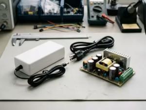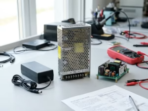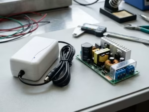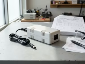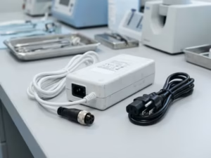
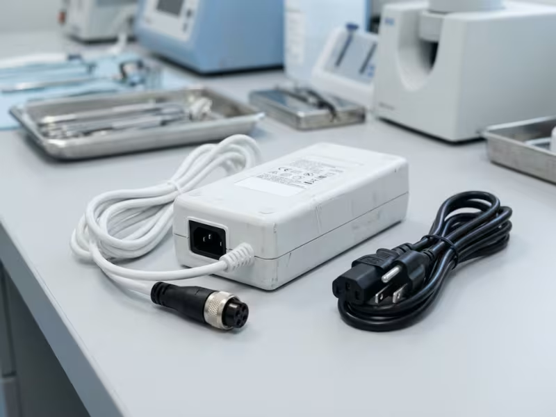
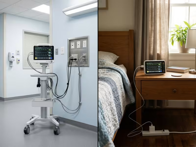
An ICU ventilator runs around the clock on hospital mains, with a UPS behind it and a biomed team down the hall. A home CPAP plugs into a bedside outlet, often with no earth pin and no one on call at 2 a.m.
Both devices keep patients breathing. Their power supplies, though, do very different jobs.
You can’t simply move the same supply into a new shell. The safety architecture, the environment, the maintenance model, and user behavior all change.
I have helped many device teams make this call. This guide shows you how to choose the right power architecture for hospital-only, home-only, and dual-use devices, especially when you compare different medical power supply options.
Why Hospital and Home-Use Devices Need Different Power Strategies
Most teams start with one question: how much power does the device need? I ask a different question first. Who will plug it in, where, and who fixes it when something goes wrong?
The answer changes the whole power brief.
A hospital device lives inside a support system. It often runs 24 hours a day and moves from patient to patient. Trained clinical staff operate it. Biomed engineers inspect it on a schedule. The building gives it earthed outlets, emergency power, and often a UPS. When a supply drifts or fails, someone notices within minutes and swaps the unit.
A home device has none of that. A patient or family member plugs it into the nearest outlet. That might be an old power strip behind the bed, shared with a space heater. The device may sit unplugged for hours, then run all night. Nobody inspects it. Support often means a phone call and a replacement unit shipped in two days.
The same failure can lead to very different outcomes. Picture a supply that drops out for three seconds during a mains dip.
In an ICU, the ventilator rides through on its internal battery or the facility UPS. An alarm sounds, a nurse checks the patient, and biomed pulls the unit that afternoon. The event becomes a service ticket.
At home, an oxygen concentrator may shut down on the same dip and fail to restart on its own. The patient is asleep. The alarm must wake someone, and the device must return to normal operation without a technician. If the restart logic or alarm power depends on the main supply, that three-second dip becomes a real patient risk.
That’s why I never treat home use as the easier case. In many ways, it’s harder. A home-use supply must:
- Tolerate poor wiring, missing earth, and unpredictable surges
- Survive drops, tugged cables, and curious pets
- Run cool and quiet in a bedroom
- Fail in a way a lay user can understand and recover from
- Last for years with no scheduled maintenance
Hospital supplies face tough demands too, mainly continuous duty and crowded electrical environments. But the hospital absorbs many risks for you. At home, the power supply has to carry those risks itself.
So the use setting isn’t a label you add at the end. It decides what your supply has to protect against.
The Two Fastest Ways to Misjudge the Power Supply
Most wrong power choices I see don’t start with bad math. They start with two assumptions that sound reasonable in a kickoff meeting. Both feel safe, and both can lead to a failed test or a wave of field returns.
Here is where each one breaks down.
“Hospital-Grade Will Cover Home Use Too”
The logic seems sound. Hospitals feel like the tougher setting, so a hospital supply should handle a bedroom. It doesn’t work that way.
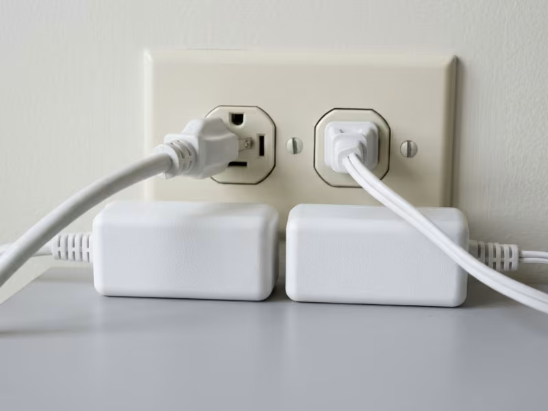
Earth dependence is the first gap. Many hospital supplies use Class I designs. They rely on protective earth for part of their safety. In a home, that earth may be missing, broken, or cut off by a two-prong adapter. The supply then loses a layer of protection your design counted on.
EMC is the next gap. Home use calls for 10 V/m radiated immunity instead of 3 V/m, plus stricter Class B emission limits. A supply that runs cleanly beside a ventilator rack can glitch next to a Wi-Fi router or a cheap LED dimmer.
Then there’s the user. A nurse won’t yank the cord to move a bed or share an outlet with a hair dryer. A tired caregiver might. And no biomed team will spot a frayed cable before it fails.
“It’s Only 30 W, So It Should Be Simple”
Low power feels like low risk. In practice, small home devices often face tighter limits than large hospital units.
Compare a 400 W hospital imaging cart with a 30 W home patient monitor. The cart sits in a ventilated room on earthed mains, often with Type B parts. The monitor connects to the patient for hours, may use BF or CF parts, and lives in a sealed, fanless case. Its supply must fit 2 MOPP spacing into a small housing, keep leakage low, and stay cool against bedding.
Small devices also stay plugged in for months. Standby draw, surface heat, and coil whine matter far more beside a bed than in an ICU.
So judge the supply by the risks it must carry on its own, not by its grade label or its wattage.
What Changes First: Safety Architecture and Certifications
Before I look at efficiency or size, I check two things: how the device touches the patient and where it will plug in. Those answers set the safety architecture. That architecture then limits almost every other power choice.
Three areas shape it most.
Applied-Part Risk Sets the Isolation Path
IEC 60601-1 sorts applied parts by how closely they connect to the patient. That class sets your leakage budget.
- Type B parts may connect to earth and suit low-risk contact.
- Type BF parts float and allow 100 µA of patient leakage in normal conditions.
- Type CF parts can reach the heart and allow only 10 µA.
The leakage limit decides how much Y-capacitance you can place across the isolation barrier. A CF design leaves very little room for EMC filtering. It often pushes you toward shielded transformer windings and larger common-mode chokes.
Next comes protection count. Operator-only equipment needs Means of Operator Protection (MOOP). Once a patient sits in the circuit, the rules shift to Means of Patient Protection (MOPP), with wider spacing and tougher tests. Most patient-connected designs need 2 MOPP from mains to patient in total.
Don’t stop at the label, though. Trace the real path from the AC inlet to the patient. If the device has its own isolated front end, the supply may carry only part of the load. If the sensor connects straight to the DC output, the supply must carry all of it.
What IEC 60601-1-11 Adds for Home Use
The home healthcare standard starts from a simple idea. The person using the device is not a clinician, and the room is not a hospital.
That idea changes your design targets in four ways:
- Lay operators. The supply must fail in a way an untrained person can see and safely recover from.
- Wider environments. Temperature, humidity, and storage ranges grow wider. A supply may sit in a cold car trunk, then run in a warm bedroom.
- Rough handling. Expect drop, shock, and vibration tests, plus protection against spills and dripping water.
- Markings and instructions. Labels must stay legible after years of cleaning. Instructions must use plain language.
For the power supply, this usually means a sturdier housing, better strain relief, and wider thermal derating. It also means you can’t assume someone will notice a problem early.
Class I vs Class II: Who Carries the Earth Risk?
This choice often decides whether one supply can serve both settings.
A Class I supply uses protective earth as one layer of protection. That works well in hospitals, where staff test outlets and installations follow strict wiring rules. Class I also helps EMC, because Y-capacitors can route common-mode noise to earth. For high-power carts, racks, and fixed systems, Class I often remains the practical choice.
A Class II supply uses double or reinforced insulation and needs no earth. At home, an earth pin may be missing, broken, or defeated by a two-prong adapter. A Class II design doesn’t care. That’s why IEC 60601-1-11 pushes home equipment strongly toward Class II or internally powered designs.
Class II has a cost. With no earth path for noise, you must solve EMC inside a tight leakage budget. I tell clients to plan the filter design and the input class together, from the first schematic. If a device might ever ship to homes, start with Class II. Converting a Class I design later usually means a new transformer, a new layout, and a new round of testing.
Performance and Reliability: What the Environment Does to the Power Path
Two supplies can share the same datasheet and still behave very differently once they leave the lab. The environment adds new tests. It also changes which performance traits matter most.
I check three areas first: how the device rides through power loss, how it handles heat, and how it copes with electrical noise.
Hold-Up Time and Backup: Who Covers the Gap?
A hospital gives the device several safety nets. A good supply holds its outputs for 10 to 20 ms through a short dip. The facility UPS covers longer events, and essential circuits switch to generator power within about 10 seconds. Critical devices also carry an internal battery.
In this setting, I focus on clean handover. The supply must recover smoothly when mains returns, with no output spike and no false reset.
At home, the device’s own design provides the only backup. No UPS sits behind the outlet. A storm, a tripped breaker, or a pulled plug lasts as long as it lasts.
That shifts the priority from hold-up time to battery strategy. Answer three questions early:
- Does the battery keep therapy running, or only power the alarm?
- Does the device restart on its own, in a safe state, when power returns?
- Can a lay user swap or charge the battery without tools or confusion?
Portable devices add one more load. The supply often charges the battery and runs the device at the same time, sometimes inside a warm carry bag. Size the supply for that combined load, not for the device alone.
Heat, Noise, and Standby Power
Hospital supplies often sit in carts or racks with planned airflow. Many clinical teams still avoid fans, because fans move dust and make cleaning harder. I usually derate hospital designs for a controlled 40°C ambient, with extra margin for stacked equipment.
Home supplies face a messier thermal picture. An adapter may lie under a blanket, behind a nightstand, or on carpet. A fan would keep a patient awake, so nearly every home supply runs fanless. That demands higher efficiency, lower-loss parts, and surface temperatures that stay safe to touch.
Standby draw matters more at home too. A CPAP or monitor may stay plugged in for months while it sits idle. I target under 0.1 W no-load on small adapters. That cuts idle heat and avoids a warm adapter that worries a caregiver.
Listen for coil whine as well. Nobody notices a faint buzz in an ICU. In a silent bedroom at 3 a.m., it turns into a support call.
EMC: Known Noise vs Unknown Noise
Hospitals create strong but predictable interference. Electrosurgical units throw out bursts of RF. Monitors, pumps, and ventilators share racks and power strips. Still, biomed teams control installations and keep wiring in good shape, so you can test against known sources.
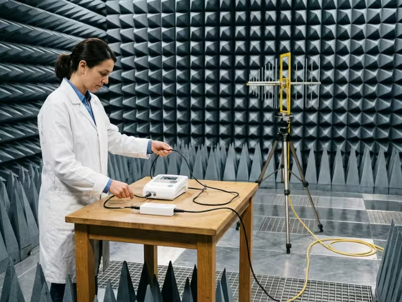
Homes create weaker but random interference. Your supply shares outlets with phone chargers, LED dimmers, Wi-Fi routers, and old vacuum cleaners. Carpets build static. IEC 60601-1-2 reflects this with 10 V/m radiated immunity for home use, compared with 3 V/m in professional settings.
The real challenge comes from your earlier choices. A Class II home supply has no earth path for noise, and its leakage limit caps Y-capacitance. So I build in margin from day one: at least 6 dB below emission limits, plus immunity tests at home levels with the real cable attached.
In a hospital, the building shares the load. At home, the power supply carries it alone.
Mechanical Design and Human Factors Change More Than Most Teams Expect
Engineers often treat the housing and cable as packaging work. In patient care, they’re safety work. Where the supply sits, how people handle it, and what they wipe it with can decide whether it lasts five years or fails in five months.
I look at three areas when I review a design for either setting.
Where the Supply Lives and How People Move It
Hospital supplies usually get a planned home. They mount inside carts, racks, or wall systems with set airflow paths and fixed cable routes. Staff seldom touch the supply itself.
Home supplies get no such plan. An adapter ends up on carpet, wedged behind a nightstand, or dangling from a bedside outlet. Patients carry portable units from room to room, and the cable takes most of the abuse. People trip on it, roll chairs over it, and wrap it tightly around the adapter for travel.
That’s why I treat strain relief as a core spec for home devices. Ask your supplier for flex test data at both cable ends. Look for a molded strain relief, not a simple grommet. Right-angle DC plugs also help, because they reduce leverage when someone bumps the device.
Connectors and Feedback a Caregiver Can Trust
Wrong-plug mistakes rarely happen in hospitals. Clinical staff work with standard equipment and follow set routines. At home, a drawer may hold three similar black adapters. A caregiver can easily plug a 19 V laptop charger into a 12 V monitor with the same barrel size.
Keyed, locking, or uncommon connectors block that mistake. I steer clients away from standard 5.5 × 2.1 mm barrels on any home device that connects to a patient. A unique pinout costs little and prevents a whole class of field failures.
Feedback matters just as much. A nurse can read a blink code. A worried spouse at midnight can’t. Keep indicators simple: one steady light for normal power and a clear, distinct alarm for loss of power. If the device runs on battery, show that state plainly. When signals stay obvious, caregivers don’t need to guess.
Cleaning Chemicals and Material Choices
Hospitals clean hard and often. Staff wipe surfaces with alcohol, quaternary ammonium compounds, bleach, or hydrogen peroxide, sometimes several times a day. Homes use a wider and less predictable mix, from kitchen sprays to ammonia-based glass cleaners.
Both settings attack plastics, but in different ways. Some polycarbonate housings crack around screw bosses and the cable entry after repeated wipes with harsh disinfectants. Labels fade, and soft cable jackets turn sticky or brittle.
Ask your supplier which cleaning agents they have tested the housing, label, and cable against. For hospital use, match that list to the disinfectants your customers actually use. For home use, test against common household cleaners as well.
A supply that survives the lab but cracks after a year of wiping still counts as a failed design.
Where Hospital and Home-Use Power Selections Usually Go Wrong
Most power supply failures in patient care don’t trace back to a bad part. They trace back to a reasonable assumption that nobody checked. I see the same five mistakes in monitors, respiratory devices, and infusion systems. Each one tends to surface late, often in the test lab or after the first field returns.
Here is how each one plays out, and what to do instead.
Mistake 1: Treating a Hospital Certificate as a Home-Use Pass
A team moves a proven bedside monitor into a home-care program. The supply already carries a 60601-1 CB report, so they reuse it as is.
The problem shows up in the report’s scope. The lab tested the supply for a professional healthcare setting, with 3 V/m radiated immunity and a trained operator. It never assessed home-level immunity, drop tests, or lay-user markings under IEC 60601-1-11. The certificate is valid, but it covers the wrong environment.
Do this instead: Read the test report’s stated environment and standards list before you reuse any supply. If home use isn’t in scope, plan for added testing from the start.
Mistake 2: Checking the Certificate but Not the Power-Loss Plan
Certification tells you the supply is safe. It doesn’t tell you what your device does when power disappears.
I reviewed one home monitor that passed every safety test. During a brownout, however, its supply sagged slowly instead of cutting off cleanly. The processor reset halfway, lost the patient’s alarm settings, and came back with factory defaults. Nobody had tested a slow brownout, only a clean on-off cycle.
Do this instead: Test dips, slow brownouts, and repeated plug-pull cycles with the real device attached. Confirm that the alarm still works, settings survive, and the device restarts in a safe state with no one present.
Mistake 3: Testing EMC and Cables in Lab Conditions Only
Lab setups are tidy. Homes are not. A supply that passes with a neat 1.5 m cable on a test table can fail when a patient adds a 3 m extension cord, coils the slack behind the bed, and shares the outlet with a dimmer and a router.
Cables fail mechanically too. Home users wrap cords tightly around the adapter, pinch them in doors, and pull the plug by the cord. After a few months, conductors break inside the jacket and cause intermittent dropouts. Those dropouts look like random device faults, so teams often chase software bugs first.
Do this instead: Run immunity tests at home levels with the longest cable you allow. Ask your supplier for flex-life data at both cable ends, and review your first field returns for intermittent power complaints.
Mistake 4: Counting on an Earth Pin the Home May Not Have
Some designs use protective earth to meet part of their isolation requirement, often through an earthed secondary or shield. In a hospital, that works. Staff test the outlets.
At home, the earth may never reach the device. Older houses have ungrounded outlets. Users plug three-prong cords into cheap two-prong adapters. The device still powers on and looks fine, but it has quietly lost a means of protection, and leakage current can rise toward the patient.
Do this instead: For any device that might reach a home, design the isolation to stand without earth. In most cases, that means a Class II supply with 2 MOPP built in.
Mistake 5: Judging the Adapter Instead of the System
The most expensive mistake hides in plain sight. A team qualifies the adapter on its own and assumes the device will behave the same way.
Then the system shows its own behavior. Leakage from the adapter adds to leakage from the device and pushes the total past the limit. Battery charging and full therapy load hit at the same moment and trip the supply’s overcurrent protection. A motor or pump starts up and creates noise that the adapter alone never produced.
Do this instead: Run leakage, thermal, and EMC pre-scans on the complete device with the real supply installed. Include the worst case: low battery, full load, maximum ambient, and the longest cable. Do this before formal testing, while design changes still cost very little.
Each of these mistakes shares one root cause. Teams evaluated the supply in the setting they knew best, not the setting where it would actually run. When you test against the real environment and the full system, these problems surface on your bench instead of in a patient’s home.
How to Choose the Right Power Architecture
By this point, you know what can go wrong. Now you need a process that keeps it from happening on your project. I walk device teams through the same five steps, in this order, before they request a single quote.
Each step builds on the one before it. Skip one, and the later steps rest on guesswork.
Step 1: Define Where the Device Will Actually Be Used
Start with the real use setting, not the one in the launch plan. Ask your product and sales teams where the device could end up within five years.
Most devices fall into one of three groups:
- Hospital only. Fixed installations, carts, and clinical systems with trained staff.
- Home only. Devices that patients or caregivers set up and run themselves.
- Both. Devices that leave the hospital with the patient, such as pumps, monitors, and respiratory units.
Be honest about the third group. If there’s a real chance the device goes home, design for home now. Adding home use later often means a new supply and a new round of testing.
Your output: A one-line use statement, such as “Hospital and home, lay operator, no guaranteed earth.”
Step 2: Map the Patient Contact and Applied-Part Risk
Next, list every part that touches or may touch the patient. Classify each one as Type B, BF, or CF.
Then trace the path from the AC inlet to each contact point. Mark every barrier along the way: the supply’s transformer, any isolated front end, and protective earth. This shows how much protection the supply must provide by itself.
A BF sensor with an isolated front end puts less load on the supply. A sensor wired straight to the DC output puts the full 2 MOPP burden on it. A CF part also cuts your leakage budget to 10 µA, which shapes your EMC filter.
Your output: An applied-part list and a one-page isolation diagram, with each barrier’s MOPP count marked.
Step 3: Decide the Input Class and Backup Strategy
Now pick how the supply connects to mains and what happens when mains disappears. Make these two choices together, because they affect each other.
For input class, use this rule:
- Hospital only, higher power, fixed install: Class I often works well and eases EMC.
- Home or dual use: Start with Class II. It doesn’t depend on an earth pin the home may lack.
For backup, match the strategy to the risk:
- Hospital UPS plus hold-up time suits devices that only need to ride through short dips.
- An internal battery suits life-supporting or alarm-critical devices in any setting.
- A swappable or external battery suits portable home devices, as long as a lay user can change it safely.
Size the supply for battery charging and full device load at the same time.
Your output: A written input class, backup method, and the worst-case combined load in watts.
Step 4: Check Environmental and Usability Demands
With the architecture set, test it against the real world. I run through this list with every client:
- EMC: 3 V/m for professional settings, 10 V/m for home. Target at least 6 dB of emission margin.
- Temperature: Derate for 40°C hospital ambient, and check home cases like bedding or a warm carry bag.
- Drop and abuse: Plan for drop, strain relief, and spill tests on home devices.
- Cleaning: List the disinfectants and household cleaners the housing must survive.
- User interaction: Choose keyed connectors, simple power and battery indicators, and plain-language instructions.
Each item becomes a line in your supplier’s requirements, not a note in someone’s head.
Your output: An environmental and usability spec sheet, with a target value for each item.
Step 5: Validate Early With Your Supplier and Lab
Before you approve a supply, ask for its CB test report. Check the stated environment, the MOPP rating, the leakage figures, and the standards list, including IEC 60601-1-11 for home use.
Then test the full system early. Install the real supply in a prototype and run leakage, thermal, and EMC pre-scans. Use the worst case: maximum ambient, full load, low battery, and the longest cable you allow.
Finally, book a short review with your test lab. Bring your isolation diagram and spec sheet. Ask the reviewer to confirm your input class and MOPP choices in writing.
Your output: A reviewed CB report, pre-scan results with margin, and written lab agreement.
When you finish these five steps, you hold a short, clear package: a use statement, an isolation diagram, an architecture choice, a spec sheet, and early test data. Send that package to any supplier, and you’ll get a quote built for your real device, not a guess. This is also the point where many teams start comparing custom power adapter options instead of forcing a standard unit into the wrong use case.
Three Devices, Three Different Power Answers
Frameworks help, but most teams recognize their own project faster through a real device. These three cases come up again and again in my work. Each one starts from a similar patient care goal and ends with a very different power design.
Look for the scenario that sounds most like your device.
The ICU Ventilator: A Power Path That Never Gets a Day Off
Picture a ventilator in a busy ICU. It runs for weeks on one patient, then gets cleaned and moved to the next bed. It rarely powers off for long.
The hospital gives this device strong support. It plugs into a red emergency outlet. If mains fails, the generator takes over within about 10 seconds. An internal battery covers that gap and supports bed-to-bed transport.
That support doesn’t make the supply’s job easy. It just shifts the focus to three things.
- Continuous duty. Size the supply for full load around the clock at 40°C ambient, not for an average load. Electrolytic capacitors set the lifetime, so ask for a calculated life at your real internal temperature. On ventilator projects, I look for well over 50,000 hours.
- Alarm continuity. The alarm must never go silent because the main rail dropped. I want a power-fail signal from the supply, such as AC OK, at least a few milliseconds before the outputs fall. That gives the controller time to switch to battery and log the event cleanly.
- Clean recovery. When the generator kicks in, dozens of devices restart at once. Check inrush current and make sure the supply recovers without a false reset.
Service is simple by comparison. Biomed pulls the unit, swaps a module, and returns it. So a field-replaceable internal supply often makes sense here.
The Home CPAP or Oxygen Concentrator: Quiet, Cool, and Hard to Break
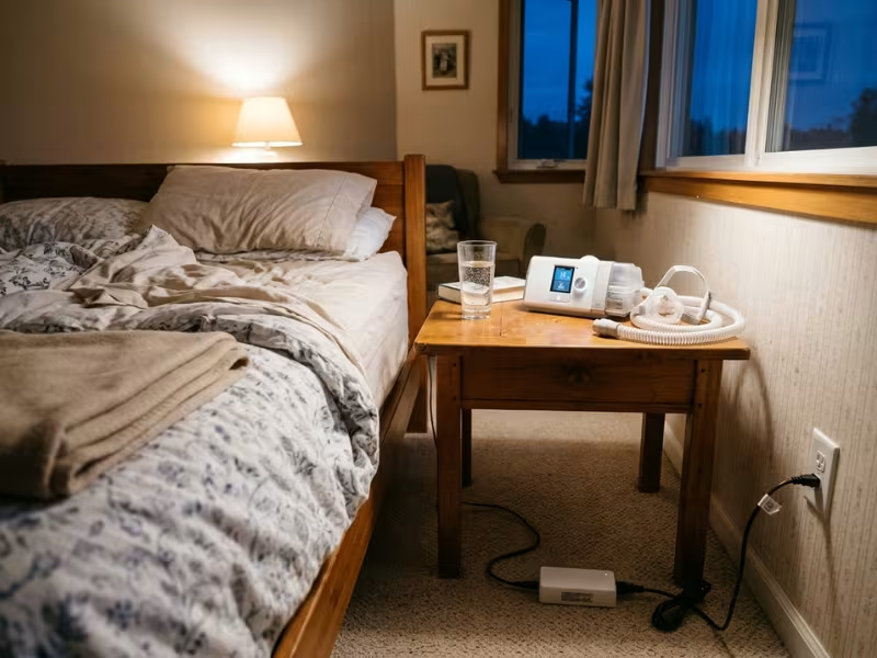
Now move to a bedroom. A CPAP sits on a nightstand next to a heated humidifier. Its external adapter lies on the carpet behind the bed, plugged into a two-prong outlet.
This supply has no backup building behind it. It has to handle everything itself.
- Class II input. Start here. The home may have no earth, so the supply needs double or reinforced insulation and 2 MOPP built in. Expect a harder EMC design, because you can’t route noise to earth.
- Real load, not label load. A CPAP may draw 30 W on its own. Add a heated tube and humidifier, and peaks can climb past 80 W. Size the supply for that combined load inside a warm, enclosed spot.
- Quiet and cool. The patient sleeps a foot away. The design should have no fan and no coil whine, with a surface that stays comfortable to touch. Keep no-load draw under 0.1 W, because many users leave it plugged in all day.
- Restart and alarms. Decide what happens after a 3 a.m. power cut. A CPAP should resume therapy on its own, with saved settings. An oxygen concentrator needs a battery-backed power-loss alarm loud enough to wake someone.
- Misuse. Users unplug the adapter daily, wrap the cord tightly, and pack it for travel. Ask for flex-life data, a molded strain relief, and a 100–240 VAC universal input for trips abroad. Plan for humidifier water nearby, too.
The Infusion Pump That Leaves With the Patient: One Supply or Two?
This case causes the most debate. A pump starts on an IV pole in a hospital ward. Two days later, it goes home with the patient for weeks of antibiotic therapy.
The device now needs two lives. In the hospital, it may draw power through a pole-mounted rack and share outlets with other equipment. At home, it runs from a bedside adapter, with a caregiver who has never read the manual.
You have two real options.
- One supply built to home levels. You certify a single Class II adapter to IEC 60601-1 and IEC 60601-1-11, with 10 V/m immunity. You get one CB report, one part number, and one change-control file. Unit cost runs a little higher, and the EMC work gets harder.
- Two variants. You use a Class I internal module for hospital racks and a separate home adapter. Each one fits its setting well. But you now manage two safety files, two supply chains, and two sets of change notices. Service gets messier, too. Sooner or later, someone ships the hospital variant to a patient’s home.
In most dual-use projects, I recommend the single home-rated supply. The extra design effort costs less than years of managing two variants. I only choose two variants when the hospital version must power a multi-channel rack that a home adapter can’t carry.
Whichever path you choose, make the adapter easy to tell apart. Use a keyed connector, a clear label, and a distinct color. When a caregiver opens the box at home, they should never have to guess which cable belongs to the pump.
FAQs About Medical Power Supplies for Patient Care
Buyers and engineers often ask me these questions when they compare hospital and home power designs. Here are short, direct answers.
What is the difference between a medical-grade power supply and a commercial one?
Most commercial supplies certify to IEC 62368-1, the standard for IT and audio-video equipment. A medical-grade supply certifies to IEC 60601-1. It needs wider creepage and clearance, often 2 MOPP with a 4,000 VAC test, much lower leakage current, and a safety file a lab can review.
You can’t close these gaps with a new label. They come from the transformer and the board layout.
What does IEC 60601-1-11 add for home-use medical devices?
It assumes a lay operator and a room nobody controls. The standard widens environmental ranges, adds drop and dripping-water tests, and requires durable labels and plain-language instructions. Paired with the 10 V/m home immunity level in IEC 60601-1-2, it usually means a tougher housing, better strain relief, and wider thermal derating.
Can the same power supply be certified for both hospital and home use?
Yes. Certify one supply to IEC 60601-1 and IEC 60601-1-11, with home-level EMC immunity. A home-rated supply usually covers hospital use too, but the reverse rarely holds.
Always check the stated environment in the CB report, not just the standard number on the cover.
Do home-use medical devices always need Class II inputs?
Not always, but start there. Home outlets may lack a working earth, and users often bypass earth pins with two-prong adapters. Devices that run on internal batteries during use avoid the question entirely.
Class I can work at home only if you prove the design stays safe when earth disappears. Labs review that argument closely.
Why is battery or hold-up strategy so important in patient care devices?
A power loss can quickly become a patient risk. In a hospital, hold-up time, the UPS, and the generator share the job. At home, the device’s own battery is the only backup.
Decide early whether that battery runs therapy or only the alarm. Then confirm the device restarts safely and keeps its settings after real-world power loss.
What should buyers ask a medical power supply supplier before approval?
Ask for proof, not promises:
- The CB test report. Check its stated environment, MOPP rating, leakage figures, and standards list.
- Capacitor life data. Get it at your real internal temperature.
- Cable and standby data. Ask for flex-life results and no-load power.
- Production testing. Confirm 100% hipot testing on every unit, and review the supplier’s production and testing facilities if you can.
- Change notice. Get written terms that promise at least 90 days’ notice before any critical part changes.

Match the Power Supply to the Room It Will Live In
Moving a device from an ICU to a bedroom doesn’t just change its address. It changes what the power supply must protect against.
In a hospital, the building shares the load with earthed outlets, a UPS, and a biomed team. At home, the supply carries that load alone. That shift reshapes your safety architecture, input class, backup strategy, thermal design, and every signal a caregiver sees.
So treat the use setting as your first design input, not a label you add before launch. Before you lock the power architecture or request a single quote, put five answers on one page:
- The patient contact type
- The real use environment
- The backup path
- Your Class I or Class II assumption
- Your EMC and thermal risks
When those five answers line up, the right supply becomes easy to spot. If you skip them, your test lab or your first field return will find the gaps for you.