A medical power supply can pass every functional test and still fail its leakage check. When that happens, the lab report stalls, the launch slips, and the team has to rethink its supply choice.
I work with engineering teams that choose medical power supplies for patient-connected devices. Most of them know the standard well. They still get caught by three things: a datasheet they read too quickly, test conditions they misjudge, and a system leakage budget nobody tracks.
Leakage current is a real limit with real consequences. It decides how safe your device stays near a patient, how smoothly approval goes, and which supplies you can use.
This guide shows you which leakage type matters most for your device and how the limits shape your design. It also explains how to read test results and datasheets correctly.
Why Leakage Current Becomes a Bigger Problem in Medical Power Supplies
Leakage current takes a path you never designed. It flows from live parts through insulation, Y-capacitors, and stray capacitance, then looks for a way back to earth. Every mains-powered product leaks a little. What matters is where that current goes and who stands in its way.
In an office product, that path usually ends at a healthy adult’s hand. In a medical device, it can end in three places:
- The enclosure. Current reaches a nurse or patient who touches it.
- An applied part. Current travels down an ECG lead or SpO2 clip straight to the patient.
- The protective earth. Current returns safely until the ground wire breaks. Then it turns into touch current.
Medical limits are tighter because the patient faces far worse exposure. Dry, intact skin adds a lot of resistance. Most adults feel current around 1 mA and can still let go of a source below roughly 10 mA. A sedated patient can’t pull away. Gel electrodes and wet skin cut the body’s resistance sharply, and a catheter or pacing lead can bypass the skin entirely.
That last case creates the risk engineers call microshock. When current enters near the heart, as little as 50 to 100 µA can trigger ventricular fibrillation, and the patient may feel nothing first. That’s why IEC 60601-1 caps CF patient leakage at 10 µA in normal condition. IEC 62368-1, by contrast, allows 0.5 mA of touch current for ordinary users.
Medical limits aren’t stricter because medical products are premium. They’re stricter because the current lands on a far more fragile target.
These limits apply to the finished device, not to the power supply alone. That is why a supply that passes on its own can still fail in the final system.
I see the cost of underestimating this in most troubled projects I review. The pattern repeats. A supply leaks 70 µA on its own and looks fine on paper. Then the display, embedded PC, and EMI filter push the total past 100 µA at the lab’s 264 V test. The report fails, the team swaps the supply, reworks the filter, and books a second EMC run. That can add weeks or even months.
The field risk runs deeper. Capacitors drift, insulation ages, and hospitals plug several devices into one power strip. A design that launches with no margin can cross the limit during an IEC 62353 recurrent test. In the worst case, it crosses that limit at a patient’s bedside.
So treat leakage as a design boundary from your first schematic, not a number you check at the end.

Start with the Real Question: Which Leakage Current Type Matters in Your Device?
IEC 60601-1 defines four leakage current types. Most devices don’t need equal attention on all four. A lab analyzer and an ECG monitor can use the same supply and still fail for completely different reasons.
When a team brings me a leakage problem, I start by asking where the current can end up. That answer tells me which number will decide the test result. The four types below follow the same order I use, from the ground wire to the patient.
Earth Leakage Current: The Number That Hides Behind the Ground Wire
Earth leakage current flows from mains parts through insulation and filter components into the protective earth conductor. Only Class I equipment has this path, because only Class I devices have a protective earth.
Most of it comes from three places:
- Y-capacitors from line and neutral to earth, which usually account for the largest share.
- EMI filter modules, which often hide extra line-to-earth capacitance inside a metal can.
- Insulation impedance and stray capacitance in transformers and heatsinks.
The limit looks generous. IEC 60601-1 allows 5 mA in normal condition and 10 mA in single fault. Teams relax when they see that, and that’s the trap.
Earth leakage only stays harmless while the earth wire stays connected. When the lab opens the protective earth, the same current flows through whoever touches the enclosure. A single 4.7 nF Y-capacitor passes about 470 µA at 264 V and 60 Hz. That nearly consumes the 500 µA single-fault touch limit by itself.
So for any grounded cart, imaging console, or metal-chassis device, read earth leakage as future touch current.
Touch Current: The Limit Every Medical Device Has to Meet
Touch current flows from the enclosure or any accessible conductive part through a person to earth. That includes metal housings, screws, connector shells, USB ports, and heatsinks that poke through a vent.
The limits are 100 µA in normal condition and 500 µA in single fault. Compare that with the 0.5 mA many ITE power supplies allow in normal use.
Class II designs need the closest look. Without a protective earth, Y-capacitors usually bridge primary to secondary. Their current then appears on every accessible part tied to the secondary. A plastic adapter can pass easily while the metal USB port on your device fails.
Even devices with no patient contact can’t ignore this number. A nurse can touch your enclosure with one hand and the patient with the other. A patient can also reach for a device on the bedside table. If your product counts as medical electrical equipment, the touch limit applies regardless of applied parts.
I tell teams to list every accessible metal part before layout. Each one is a test point the lab will probe.
Patient Leakage Current: The Most Sensitive Number in the Report
For any device that touches the patient, this type usually decides the outcome. Patient leakage current flows from the applied part through the patient to earth. It can also appear when an outside voltage lands on the patient and drives current back through your device.
The applied part type sets the target:
- Type B: 100 µA normal, 500 µA single fault. The applied part may connect to earth.
- Type BF: The same 100 µA and 500 µA limits, but the patient connection must float behind an isolation barrier.
- Type CF: 10 µA normal, 50 µA single fault. These parts can create a direct path to the heart.
The lab also checks total patient leakage when you have several applied parts. For CF, that total stays at 50 µA in normal condition. Four ECG leads and an invasive pressure channel all share that budget.
The mains-on-applied-part test is the hardest one for floating designs. It applies mains voltage to the patient connection and measures the result. A CF part must hold that current to 50 µA. In practice, barrier capacitance decides that number. About 100 pF across your isolated DC/DC converter can use up the entire 10 µA normal-condition CF budget at 264 V.
That’s why I ask for the coupling capacitance of the patient-side converter before any other spec on CF projects.
Patient Auxiliary Current: Small, Specific, and Easy to Miss
Patient auxiliary current flows between applied part elements during normal use. It does not serve a physiological purpose. It comes from the measurement electronics themselves.
Common sources include:
- ECG lead-off detection, which injects a small bias current to check electrode contact.
- Impedance pneumography, which drives a high-frequency signal across the chest to measure breathing.
- Bioimpedance sensing in body composition and cardiac output devices.
The DC limit is strict at 10 µA in normal condition for every applied part type. The AC limit follows the patient leakage pattern, which is 100 µA for B and BF and 10 µA for CF.
A single-sensor device, such as a temperature probe, rarely needs much attention here. Multi-channel monitors and multi-function devices need far more. Each added channel adds another possible current path between electrodes on the same patient.
The power supply rarely causes this current directly. However, a shared isolated rail or a ground loop between channels can push a borderline front end over the line. If your device places two or more electrodes on the same patient, give this number its own row in your leakage budget.
Leakage Type | Where It Flows | When It Matters Most | Main Design Concern |
|---|---|---|---|
Earth leakage | Mains parts to protective earth | Class I, metal-chassis equipment | Total Y-capacitance and filter modules |
Touch current | Accessible parts through a person | Every ME device, especially Class II | Primary-to-secondary Y-caps, exposed metal |
Patient leakage | Applied part through the patient | BF and CF devices | Barrier capacitance, mains-on-applied-part |
Patient auxiliary | Between applied part elements | Multi-channel monitors, impedance sensing | Front-end bias currents, shared rails |
Pick the row that matches your highest-risk connection. That row sets your design priorities.
What the IEC 60601-1 Limits Actually Mean for Design Decisions
Most teams read the IEC 60601-1 limits as pass/fail lines on a lab report. I read them as design rules. Each limit tells you how much Y-capacitance you can afford, how good your isolation barrier must be, and which supplies belong on your shortlist.
The limits make more sense once you see how they shape the architecture. Here are the areas that change designs most often.
Single Fault Usually Sets the Real Ceiling
The lab tests every leakage type twice. It measures in normal condition (NC), then repeats the test in single-fault condition (SFC). Typical single faults include an open protective earth, an open supply conductor, and mains voltage applied to a patient connection.
Many teams design to the NC number and treat SFC as a formality. That mistake is costly. The SFC limit is higher, but the fault often sends far more current down the path you’re measuring.
Take a Class I cart. Earth leakage can reach 5 mA in normal condition. But when the lab opens the earth wire, that current turns into touch current, and the limit drops to 500 µA. The open-earth fault, not the 5 mA rule, sets your Y-capacitor budget.
Here’s a rule of thumb I use. At 264 V and 60 Hz, each 1 nF from line to earth passes about 100 µA. Keep total line-side Y-capacitance well under 5 nF on a Class I design, and leave room for every other module.
Applied Part Type Decides Your Barrier
Type B and BF parts share the same patient leakage limits: 100 µA in NC and 500 µA in SFC. The difference sits in the architecture. A B part may tie to earth. A BF part must float behind a real isolation barrier, and the lab tests that barrier with mains applied to the patient connection.
CF cuts the patient limits by a factor of ten. Your isolated DC/DC converter then has to be designed around capacitance, not just voltage rating. The mains-on-applied-part limit for CF is 50 µA. At 264 V, that allows only about 500 pF of total barrier capacitance. In practice, I aim for 100 to 200 pF per patient channel to keep margin.
That one number changes your parts list. Standard isolated DC/DC modules often have 1,000 pF or more across the barrier. Few of them suit a CF design.
Leakage Type | Applied Part Class | NC Limit | SFC Limit | Design Implication |
|---|---|---|---|---|
Earth leakage | Class I equipment | 5 mA | 10 mA | Rarely the binding limit; treat it as future touch current |
Touch current | All ME equipment | 100 µA | 500 µA | Caps line-side and primary-to-secondary Y-capacitance |
Patient leakage | Type B / BF | 100 µA | 500 µA | BF needs a floating barrier rated for mains-on-applied-part |
Patient leakage | Type CF | 10 µA | 50 µA | Requires low-capacitance isolation on every channel |
Total patient leakage | Type CF | 50 µA | 100 µA | All CF channels share one budget |
The figures above reflect commonly used IEC 60601-1 references in current practice. Always confirm the exact edition, amendments, and national adoption your lab will apply.
Your Supply Only Gets Part of the Budget
A limit applies to the finished device, not to each part. Your power supply is only the first claim on that budget.
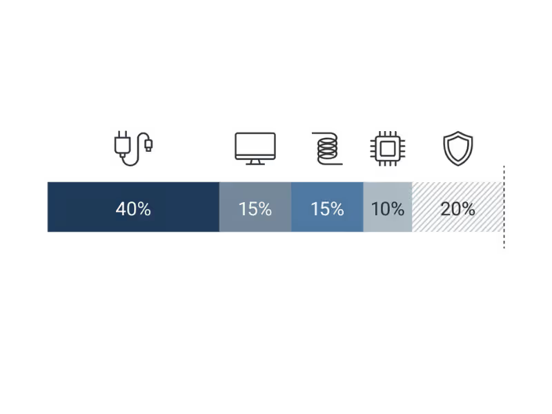
Picture a Class II bedside monitor with a 100 µA touch limit. I would split the budget like this, with every figure measured at 264 V:
- Power supply: 40 µA
- Display and embedded PC: 15 µA
- EMI filter: 15 µA
- Isolated DC/DC and patient front end: 10 µA
- Reserve for tolerance and late changes: 20 µA
Now swap in a supply that leaks 75 µA. That leaves 25 µA for four blocks and no reserve. The next EMC fix, often an extra Y-capacitor, pushes you over the line. A supply that “passes” on its own can still sink your system.
So before you approve a supply, write the device limit at the top of a sheet. Subtract the supply’s worst-case leakage, not its typical value. If the remainder can’t cover the other blocks plus 20% reserve, pick a different supply now.
Regional Versions Rarely Change the Numbers
You will see the standard under several names. The US uses ANSI/AAMI ES60601-1, which replaced the older UL 60601-1. Europe uses EN 60601-1, and Canada uses CSA C22.2 No. 60601-1. The leakage limits match closely across these versions. The differences usually show up in edition timing and national deviations.
Tell your lab every target market before testing starts, and confirm that your supplier’s CB report covers the same edition.
Treat the limits as design inputs. Settle them before schematic capture, and the rest of your power architecture gets much easier to defend.
How Leakage Current Testing Works in Practice
Most leakage failures I investigate don’t come from bad hardware. They come from a bench measurement that looked fine because the team measured under the wrong conditions.
A test lab doesn’t plug your device into the wall and read a meter. It follows a defined setup built to show your worst case, not your typical one. If your internal tests skip that setup, your numbers will look better than the lab’s.
Three things shape the result: the conditions you test under, the network you measure with, and the setup mistakes that quietly skew the reading.
Test Conditions That Change the Result
IEC 60601-1 pushes every variable toward more leakage. Expect the lab to apply all of these:
- 110% of the highest rated voltage. A device rated 100–240 V gets tested at 264 V.
- The highest rated frequency. Capacitive leakage rises with frequency, so 60 Hz reads about 20% higher than 50 Hz.
- Polarity reversal. The lab swaps line and neutral and records the higher of the two readings. An asymmetric filter or a single Y-capacitor often shows a clear difference.
- Single-fault simulation. The lab opens the protective earth, opens one supply conductor, and applies mains voltage to F-type applied parts. Each fault gets its own reading and its own limit.
Temperature and moisture matter too. For type testing, the lab first conditions the device in a humidity cabinet, typically at 93% relative humidity for 48 hours. It then measures with the device at operating temperature. Warm, damp insulation has lower impedance, so leakage creeps up. A reading taken two minutes after power-on in a dry, cool lab can come in noticeably low.
My advice is to copy these conditions on your own bench from the first prototype. A variable AC source that reaches 264 V at 60 Hz costs far less than a failed lab slot.
The Measuring Network and Why It Matters
The lab measures leakage through a defined measuring device, or MD. It models the human body as roughly 1 kΩ of resistance and adds a filter network. The instrument reads the voltage across that network and converts it to current.
The filter handles frequency weighting. The body reacts less to current above about 1 kHz, so the MD reads high-frequency components lower than raw current. This matters for switch-mode supplies, because much of their leakage sits at switching harmonics, not at 50 or 60 Hz.
That’s why a standard multimeter won’t give you a useful number. In current mode, it inserts a tiny shunt instead of a 1 kΩ body model. It applies no weighting, and its bandwidth may miss or misread high-frequency content. It also may not capture AC and DC components together as true RMS.
Use a medical safety analyzer with a built-in MD, or build the MD network exactly as the standard specifies. Then check its calibration date. A drifted network can shift CF readings by several microamps, which is a large share of a 10 µA limit.
Where Teams Get Misleading Results
These four mistakes cause most of the “but it passed on our bench” conversations I have with clients.
Testing at the wrong voltage. A reading at 115 V and 60 Hz scales by about 2.3 times at 264 V. A reading at 230 V and 50 Hz scales by about 1.4 times at 264 V and 60 Hz. A comfortable 45 µA at 115 V becomes roughly 100 µA in the lab.
Ignoring load state. Leakage can change between standby, idle, and full operation, especially when fans, heaters, or motor drivers switch in. Measure in every operating mode and record the worst one. That’s the figure the lab will report.
Oversimplifying the setup. Teams often leave out patient cables, skip the metal foil the standard applies to insulating surfaces, or test with a laptop attached through USB. That laptop can earth your secondary and hide touch current completely. Test the device exactly as it ships, with every accessory a user might connect.
Mixing up IEC 60601-1 and IEC 62353. IEC 60601-1 governs type testing during design approval. IEC 62353 governs recurrent and post-repair testing in hospitals. It measures at normal mains voltage, allows alternative and differential methods, and uses its own limits. A passing 62353 result tells you nothing about whether your design will pass type testing.
Run your pre-compliance checks the way the lab will run them. Then your first formal test confirms a number you already know.
How to Read Leakage Current Specs on a Datasheet Without Getting Misled
A leakage figure on a datasheet looks like a fact. Often, though, it shows a best case measured under conditions your lab will never use. I’ve watched teams choose a supply because its datasheet said “under 50 µA,” then lose two months when the lab recorded more than double that figure.
Once you know where to look, a datasheet takes about ten minutes to check. Start with the numbers you can trust. Then look for the gaps. Finally, put your questions to the supplier in writing.
Numbers That Actually Help
A useful leakage figure always tells you how the supplier measured it. Without that context, the number means very little. Look for these five details next to every leakage value:
- Maximum, not typical. “Typical” describes an average unit on a good day. “Max” or “≤” tells you what the supplier will stand behind across production. Y-capacitors often carry ±20% tolerance, so a typical figure can hide units that run noticeably higher.
- 264 V test voltage. Your lab tests at 110% of your highest rated voltage. To match that, scale a 115 V figure by about 2.3. Scale a 230 V, 50 Hz figure by about 1.4.
- 60 Hz frequency. Capacitive leakage rises with frequency. The same supply reads about 20% lower at 50 Hz.
- Load state. Good datasheets list both no-load and full-load values, or they state which one gives the worst case.
- Both NC and SFC. You need normal-condition and single-fault values. The supplier should also name the fault, such as an open earth.
When a supplier lists all five, you can drop the number straight into your leakage budget.
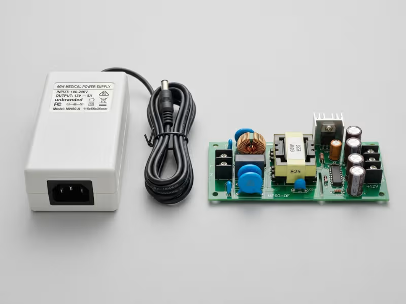
Here’s a comparison I use with clients. Both 60 W supplies claim IEC 60601-1 approval, and both target a Class II BF device with a 100 µA touch limit.
Datasheet Detail | Supply A (Encapsulated Adapter) | Supply B (Open-Frame) |
|---|---|---|
Stated touch current | < 45 µA typical | ≤ 70 µA max |
Stated conditions | 115 V, 60 Hz, load not stated | 264 V, 60 Hz, full load |
Single-fault data | Not listed | ≤ 300 µA, open earth |
Likely value at lab conditions | About 105 µA, before tolerance | 70 µA |
Budget left for the rest of the device | None | 30 µA |
Supply A looks better on paper. Under your lab’s conditions, it uses your entire budget before you connect a display or filter. Supply B shows a higher number, but you can actually plan around it.
Red Flags That Deserve a Follow-Up
None of these issues means the supply is bad. Each one means you don’t have enough evidence yet. Treat them as open questions.
Only typical values appear. If the datasheet never states a maximum, the supplier may not track the spread in production. Ask for a guaranteed limit.
No voltage or frequency is listed. “Leakage current: < 0.1 mA” with no conditions tells you almost nothing. Also watch for rounding. A spec of “< 0.1 mA” can hide a real value of 95 µA.
Single-fault data is missing. On a Class I supply, the open-earth result decides your Y-capacitor budget. Without it, you can’t check the 500 µA touch limit.
No applied part reference appears. “Medical grade” alone doesn’t confirm BF or CF suitability. Look for a stated MOPP rating and a patient leakage figure. For CF designs, you also need the primary-to-secondary capacitance in picofarads. Many datasheets leave it out.
Earth leakage appears, but touch current doesn’t. Class II supplies have no earth path. Their risk shows up as touch current on the secondary side. A datasheet that lists only earth leakage for a Class II model misses the number you need most.
The marketing sheet and the test report disagree. I see this more often than you’d expect. The brochure may say 50 µA, while the report table shows 88 µA. Sometimes the report covers a different model variant or a narrower input range. Your lab will trust the report, so you should too.
What to Ask Before Design-In
Send these questions before your team commits the supply to a schematic. A strong supplier answers within a few days and attaches proof.
- Can you send the leakage tables from the full test report? The certificate alone won’t help. You need the measured values and the stated conditions.
- What are the values at 264 V and 60 Hz? Ask for both polarities, no-load and full-load, and NC and SFC results.
- What maximum do you guarantee across production? Also ask whether the supplier runs a leakage or hipot test on every unit and which limit it uses.
- What are the total Y-capacitance and the primary-to-secondary capacitance? These two figures let you estimate leakage at any voltage. They also tell you whether the supply suits a CF design.
- Did the tested sample include an external filter or ferrite? If it did, that part becomes part of your design and your leakage total.
- Has the design changed since testing? A new Y-capacitor vendor or a revised transformer can shift leakage without changing the part number.
Once you have the answers, open your leakage budget sheet. Enter the supplier’s worst-case value at 264 V, not the typical figure from the brochure. Subtract it from your device limit. If the rest of the system can’t fit in what remains, along with a 20% reserve, move on to the next supply now.
That decision costs you an afternoon. Finding the same problem in the lab can cost you a quarter. And when no standard model can meet your leakage budget and form-factor limits at the same time, custom power adapters may be the better path.
Reducing Leakage Current Without Breaking EMC
Every leakage fix has a price, and EMC usually pays it. Pull capacitance out of one path, and noise looks for another way out. I’ve watched teams solve a leakage failure on Monday and fail conducted emissions by Friday.
The goal isn’t the lowest possible leakage number. It’s the lowest leakage you can reach while still passing CISPR 11 with margin. These are the levers I reach for first.
Size Y-capacitors against your leakage budget, not your EMI comfort zone. Y-capacitors give common-mode noise a short path home, which is why designers like them. They also carry mains current. At 264 V and 60 Hz, each 1 nF from line to earth passes about 100 µA. A design with 4.7 nF of Y-capacitance has used most of a 500 µA single-fault touch limit before anything else connects.
When you cut Y-capacitance, the noise doesn’t disappear. It shows up in the 150 kHz to 30 MHz conducted band. So you have to make up the attenuation somewhere else:
- A larger common-mode choke. More inductance replaces lost capacitance, but it adds size, copper loss, and heat.
- A two-stage filter. It works well, but it costs board space and a second set of parts to qualify.
- Quieter switching. Quasi-resonant or soft-switching topologies cut dv/dt at the source. Frequency dithering spreads peak emissions across a wider band.
I start every filter design with a fixed Y-cap ceiling from the leakage budget. Then the EMC engineer works inside it.
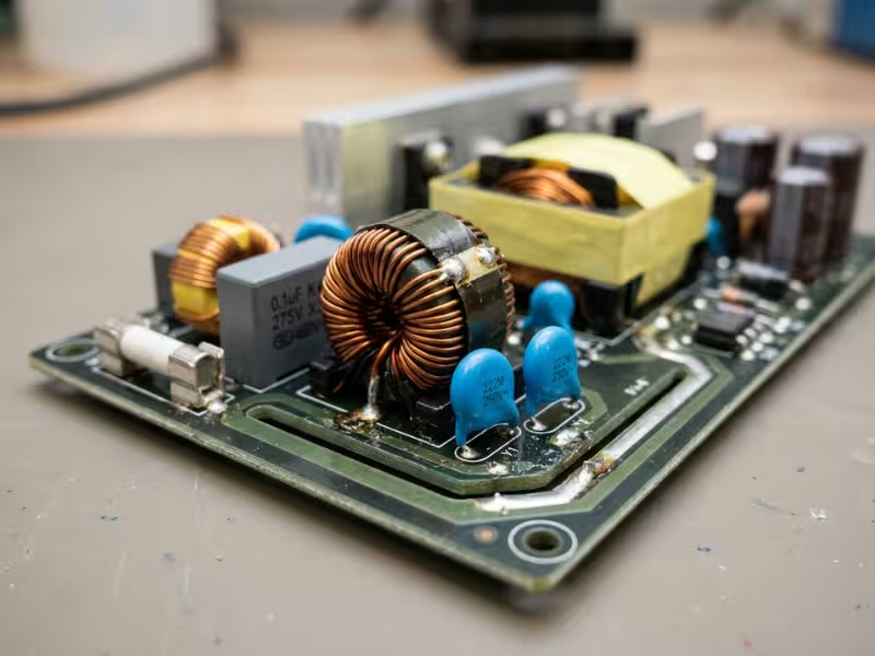
Treat transformer capacitance as a leakage source. Interwinding capacitance in a typical flyback transformer runs from about 20 to 100 pF. That couples switching noise and mains-frequency current into the secondary. A shield winding tied to the primary return helps a lot. It sends that current back where it came from instead of out to the user.
On the patient side, the isolated DC/DC converter matters even more. Standard modules often carry 1,000 pF or more across the barrier. Medical low-coupling modules can go below 20 pF. For CF designs, that single spec often decides which converter you can use.
Use insulation spacing wisely, and know what it costs. A 2 MOPP barrier needs about 8 mm of creepage and 5 mm of clearance at 250 V working voltage. Wider spacing and triple-insulated wire reduce coupling capacitance, which helps leakage. They also raise transformer leakage inductance. That means more ringing, hotter snubbers, and often more high-frequency noise. Plan a few transformer iterations instead of expecting one sample to work.
Consider an active EMI filter when the Y-cap budget gets too tight. An active filter senses common-mode noise and injects an opposing current to cancel it. In the right design, it can bring line-side Y-capacitance down from several nanofarads to a few hundred picofarads.
It isn’t a free upgrade, though. It works best at the lower end of the conducted band, so you still need passive filtering above a few megahertz. It adds active parts to your risk file. Your lab will also ask a fair question: what happens to emissions and leakage if the filter fails? Have that single-fault analysis ready before testing.
Pick a grounding scheme early and keep it consistent. In Class I designs, Y-capacitors return to protective earth, so the open-earth fault decides your budget. In Class II designs, Y-capacitors usually bridge primary to secondary. Their current then appears on every accessible metal part tied to the secondary. In either case, keep the patient-side ground floating. Never tie it to chassis just to quiet a noisy front end.
The installation matters too. Devices used on isolated IT systems in operating rooms, or on TT networks in some regions, can see different fault paths than your bench. Confirm your target power systems with your lab.
Accept that lower leakage moves cost elsewhere. Here’s how the trade usually lands:
Leakage Fix | Where the Cost Moves |
|---|---|
Smaller Y-capacitors | Larger choke, extra filter stage, more EMC iterations |
Shielded transformer | Higher transformer cost, longer qualification |
Low-capacitance patient DC/DC | Higher module cost, fewer sourcing options |
Active EMI filter | More parts, more risk analysis, single-fault testing |
Wider insulation spacing | Larger board and enclosure, more snubber loss |
None of these costs is a reason to avoid the fix. Budget for them from the start. A supply that arrives with low leakage and solid EMC margin has already absorbed much of this work. That’s often why a quality medical supply costs more and saves money at the project level.
Four Ways Teams Read Leakage Data Too Optimistically
Most leakage surprises don’t come from bad math. They come from a reasonable belief that only holds in a narrow case. I hear these four in almost every design review, usually from capable engineers who simply trusted a number too early.
Each one sounds safe on its own. Here’s where each one breaks down.
“We’ll Just Cut the Y-Capacitors”
Removing Y-capacitance is the fastest way to lower leakage on paper. It’s also the fastest way to fail conducted emissions.
Y-capacitors give common-mode noise a short path home. Take them out, and that noise moves onto the mains cable in the 150 kHz to 30 MHz band. I’ve seen a team drop from 4.7 nF to 1 nF, cut touch current from 470 µA to about 100 µA, and then fail CISPR 11 by 12 dB the following week.
Immunity can suffer too. Y-capacitors also help shunt ESD and fast transients. Without them, a front end that ran cleanly may start throwing false alarms during IEC 61000-4-4 burst testing.
So treat any Y-cap change as an EMC change. Before you remove one, decide what will replace its attenuation, such as a larger choke, a second filter stage, or quieter switching. Then rerun a quick conducted scan the same day.
“Earth Leakage Is the Only Number That Matters”
Earth leakage gets attention because it’s easy to measure and often appears first on the datasheet. On many devices, it’s the least likely number to fail.
Class II equipment has no protective earth path at all. Its risk shows up as touch current on accessible metal tied to the secondary.
Floating patient circuits carry a separate risk. A BF or CF applied part doesn’t connect to earth by design. Its leakage flows through barrier capacitance and the patient. The lab tests this by applying mains voltage directly to the patient connection. Your earth leakage reading never sees that path.
The scale matters as well. Earth leakage allows 5 mA in normal condition. CF patient leakage allows 10 µA. A device can sit at 300 µA earth leakage, far under its limit, and still fail CF because its isolated DC/DC converter carries 400 pF across the barrier.
Check every leakage type that applies to your device. Pay the most attention to the one closest to the patient.
“IEC 62353 Replaced IEC 60601-1 Testing”
It didn’t. The two standards answer different questions at different stages.
IEC 60601-1 governs type testing. It asks whether the design is safe. The lab preconditions the device in humidity, tests at 110% of rated voltage, reverses polarity, and simulates single faults.
IEC 62353 governs testing before first use, during recurrent checks, and after repair. It asks whether this particular unit is still safe in service. Hospital technicians measure at normal mains voltage, often with alternative or differential methods. They skip single-fault simulation and use limits set for field checks.
A unit that passes 62353 in a hospital tells you nothing about whether your design would pass type testing. A passed type test doesn’t remove the need for recurrent checks either.
Design to 60601-1. Then leave enough margin for 62353 tests years later, after capacitors drift and insulation ages.
“Any Certified Supply Will Work in Our Device”
A 60601-1 certificate shows that the supply is safe under the conditions in its own report. It doesn’t show that the supply suits your device.
Three gaps catch teams most often:
- Protection level. A 2 MOOP supply carries a genuine medical certificate. It still can’t serve as the patient barrier in a BF device.
- Leakage share. A supply that passes at 75 µA leaves only 25 µA for everything else under a 100 µA touch limit.
- Conditions of acceptability. The report may assume an earth connection, a certain enclosure, or a 2,000 m altitude limit that your product doesn’t meet.
Start with your end equipment’s applied part classification. Then check whether the supply’s MOPP rating, leakage figures, and report conditions fit that classification. The certificate opens the conversation. Your device’s classification decides whether that supply belongs in your design.
What Engineers and Buyers Should Confirm Before Choosing a Supply
Most leakage problems I see trace back to a supply chosen before anyone checked six basic facts. Engineers and buyers usually work from different documents, so gaps slip through. One shared checklist fixes that.
Run through these items before the supply part number goes into your schematic or your purchase order.
1. Lock the applied part classification of your end device.
Your device’s highest-risk patient connection sets the target, not the supply’s datasheet. Mark every applied part as B, BF, or CF, and note any defibrillation-proof parts. A CF requirement changes everything downstream. You need lower barrier capacitance, tighter total patient leakage, and a supply that leaves real room in the budget. If this classification is still “TBD,” stop here.
2. Confirm the test report covers both NC and SFC.
A normal-condition result alone is half the picture. Look for single-fault results with each fault named, such as open earth or open supply conductor. The report should also state the conditions: 264 V, 60 Hz, both polarities, and the load state. On a Class I supply, the open-earth touch current often decides your Y-capacitor budget.
3. Check the edition and amendment status.
Find the exact standard version on the report’s cover page. Most labs and regulators now expect IEC 60601-1 Edition 3.2, which includes Amendment 2. An older report may still be valid for the supply, but your lab may ask for a gap analysis. Confirm the report matches the edition your lab plans to apply and covers national versions such as ANSI/AAMI ES60601-1 and EN 60601-1.
4. Build the leakage budget now, not at the lab.
Write your device limit at the top of a sheet. Enter the supply’s worst-case value at 264 V, then allocate the rest to the display, EMI filter, isolated DC/DC converter, and patient front end. Hold back at least 20% as reserve. Name an owner for each line. A budget built during component selection takes an afternoon. A budget built after a failed report takes a board spin.
5. Plan for in-service testing under IEC 62353.
Your device will face recurrent tests in hospitals for years. Capacitors drift, insulation ages, and cables wear. A design that passes type testing with almost no margin can fail a routine check after a few years in service. Ask your supplier how leakage changes over life, and tell your service team which values to expect.
6. Judge the supplier by the completeness of its documentation.
A strong supplier sends the full IEC 60601-1 test report, the CB report, and the conditions of acceptability without being pushed. Read those conditions closely. They may require an earth connection, a specific enclosure, an altitude limit, or repeat temperature tests in your final assembly. If a supplier offers only a one-page certificate, treat that as missing evidence.
When all six items check out, you can defend the choice to any lab or notified body. When even one stays open, you’ve found your next task.
FAQs
What is the acceptable leakage current limit for medical devices?
No single limit applies. IEC 60601-1 sets a limit for each leakage type and each condition. These are the figures I check first:
- Touch current: 100 µA in normal condition, 500 µA in single fault
- Patient leakage, Type B and BF: 100 µA normal, 500 µA single fault
- Patient leakage, Type CF: 10 µA normal, 50 µA single fault
- Earth leakage: 5 mA normal, 10 mA single fault
These limits apply to the finished device, not just the power supply. Your supply should use only part of the budget. I aim to keep at least 20% in reserve for capacitor tolerance and late design changes.
What is the difference between patient leakage current and touch leakage current?
The difference is the path the current takes.
Touch current flows from the enclosure or any accessible metal part, through a person, to earth. That person could be a nurse, a patient, or a visitor. Every medical electrical device has to meet this limit.
Patient leakage current flows from an applied part, through the patient, to earth. Examples of applied parts include an ECG lead, an SpO2 clip, or a probe. It only applies to devices that touch the patient.
In practice, touch current depends mostly on Y-capacitors and exposed metal. Patient leakage depends on the capacitance across your isolation barrier. For CF designs, patient leakage is usually the harder limit to meet.
What is the difference between Type B, BF, and CF applied parts?
These classes describe how closely an applied part connects to the patient and how well it is isolated.
- Type B: The part touches the patient and may connect to earth. Examples include some patient tables and exam lights.
- Type BF: The patient connection floats behind an isolation barrier. SpO2 sensors, BP cuffs, and temperature probes usually fall here.
- Type CF: The part can create a direct path to the heart. ECG leads and invasive pressure lines are typical examples.
B and BF parts share the same patient leakage limits. CF cuts those limits by a factor of ten. That forces you to use low-capacitance isolated DC/DC converters on every patient channel.
How is leakage current measured in a medical power supply?
The lab measures through a measuring device, or MD. This network models the human body at about 1 kΩ and applies frequency weighting above roughly 1 kHz. A medical safety analyzer has an MD built in. A standard multimeter does not.
The lab sets up the worst case:
- 110% of the highest rated voltage, usually 264 V
- The highest rated frequency, usually 60 Hz
- Line and neutral swapped, with the higher reading recorded
- Single faults, such as an open earth or mains on the applied part
The lab also preconditions the device in humidity and measures at operating temperature. Copy this setup on your bench early so your results match the lab’s.
What is the difference between IEC 60601-1 and IEC 62353 for leakage testing?
They test different things at different stages.
IEC 60601-1 covers type testing during design approval. It asks whether the design is safe. The lab uses humidity preconditioning, 110% voltage, polarity reversal, and single-fault simulation.
IEC 62353 covers testing before first use, recurrent checks, and post-repair checks in hospitals. It asks whether a particular unit is still safe in service. Technicians test at normal mains voltage and often use alternative or differential methods. The standard also sets its own limits.
One doesn’t replace the other. Design to 60601-1. Then leave enough margin that your device still passes 62353 checks after years of capacitor drift and wear.
Does leakage current testing apply to battery-powered medical devices?
Yes, but the tests change. IEC 60601-1 treats a battery-only device as internally powered equipment. With no mains connection, earth leakage doesn’t apply. The lab still measures touch current, patient leakage, and patient auxiliary current. For BF and CF parts, it also runs the mains-on-applied-part test, which checks how your isolation holds up when an outside voltage reaches the patient.
The charger creates the main exception. If someone can use the device on a patient while it charges, the lab tests that mode as mains-powered equipment. Your charger’s leakage then counts toward the device’s total. I treat the charger as part of the leakage budget from the first schematic.
Conclusion
Leakage current isn’t a box you tick at the end of a project. It sets the limits for your Y-capacitors, your isolation barrier, and every supply you can consider. Teams that treat it as a design boundary from the first schematic rarely lose months in the lab.
Your applied part classification decides where that boundary sits. In a BF device, touch current and the floating barrier usually decide the result. In a CF device, barrier capacitance becomes the deciding number, because 10 µA leaves almost no room. Classify every patient connection first. Then build your leakage budget around the strictest one.
Before you commit to a supply, ask the supplier for the full test report, not a one-page certificate or a brochure figure. Look for measured maximums at 264 V and 60 Hz, in both normal and single-fault conditions. Enter that worst-case value in your budget. If the rest of your device still fits with margin, you have a supply you can defend in front of any lab.