BF and CF look like they differ by just one letter. But pick the wrong one, and you may redo your risk analysis, leakage tests, and lab submission from scratch. I have watched engineers lose months to that mistake.
This article is a selection guide, not a glossary.
The real question is not which rating sounds more advanced. It is what your applied part and patient current path actually demand. Answer that first, and the right power supply becomes much easier to choose.
BF and CF Start at the Patient, Not the Power Supply
Many engineers first meet BF and CF on a power supply datasheet. That’s where the confusion starts. Before we compare ratings, let’s put these labels back where they belong.
BF and CF Describe the Applied Part First
IEC 60601-1 uses BF and CF to classify applied parts. These are the parts of your device that touch the patient, such as ECG electrodes, SpO2 clips, or catheter connectors.
- A BF applied part floats, isolated from earth, and suits body contact.
- A CF applied part meets much tighter leakage limits, so it can connect directly to the heart.
The rating starts at the patient end of your device, not at the AC inlet.
A Power Supply Supports the Rating but Can’t Carry It Alone
Good medical power supplies give you a strong head start. They provide 2x MOPP isolation from mains and keep their own leakage low. That leaves room in your patient leakage budget.
But your lab tests the whole device. Leakage can reach the patient through any path from mains. Your isolated front end, signal cables, data ports, chassis, and even a connected laptop all play a part.
I once reviewed a monitor with a CF-capable supply that still measured 14 µA against a 10 µA CF limit. A USB port without isolation created the extra path. The supply was fine. The system was not.
Think of the PSU as one strong link in the chain. The applied part’s own isolation barrier still does most of the work.
Why You Should Settle This Before Calling Suppliers
If you shop first, the datasheet starts making your decisions. You may pay for CF when BF fits. Or you may trust a “BF-rated” label that only covers the supply.
Define your applied parts and patient current paths first. Then ask suppliers precise questions about leakage at 264 VAC, isolation ratings, and full test reports. Their answers will finally mean something.
BF vs CF: Where the Real Difference Lives
Both ratings rely on the same core idea: a floating applied part. The difference is how little current you may let through and where that current could end up.
BF: Built for Contact With the Body Surface
A BF applied part has no direct connection to earth, so the patient never becomes part of a ground return path.
Patient leakage must stay at or below:
- 100 µA in normal condition
- 500 µA under a single fault
Many skin-contact monitoring and therapy parts land here, such as NIBP cuffs and SpO2 finger clips. These limits give you workable headroom. A solid isolated front end and a well-chosen medical PSU can usually hit BF targets without exotic parts.

CF: Built for a Path to the Heart
A CF applied part uses the same floating isolation, but the limits drop sharply:
- 10 µA in normal condition
- 50 µA under a single fault
CF covers parts that may form a direct or indirect conductive path to the heart. Typical examples include intracardiac catheters, internal defibrillator paddles, and cardiac output monitors.
At this level, every microamp counts. Y-capacitors, barrier capacitance, and even a long shielded patient lead can each add measurable leakage. I tell clients to treat a CF budget like a tight bank account. Small charges add up fast, and you can’t overdraw it.

The Patient Current Path Decides Everything
For background, Type B sits at the bottom of the scale. Its applied part may connect to earth, so it rarely suits patient-connected designs today.
The 10x gap between BF and CF exists for one reason: cardiac tissue is far more vulnerable than skin.
Current entering through the skin spreads out and meets high body resistance. Current reaching the heart directly arrives concentrated. Currents on the order of 100 µA delivered straight to heart muscle can trigger ventricular fibrillation. The same current through skin may go unnoticed.
So don’t judge the rating by the probe tip alone. Trace the full conductive path from mains through:
- The power supply’s isolation barrier
- Your signal ground and isolated front end
- Cables, connectors, and accessories
- The point where current finally meets tissue
If any link in that chain can reach the heart, you are in CF territory.
Do You Actually Need CF? Answer This First
Many teams ask which rating is safer. The better question is where patient current can go. I sort most projects into three groups. The hard part is spotting which group yours falls into.
Cases That Usually Point to BF
BF fits when every conductive path ends at the body surface and stays there:
- Surface monitoring: NIBP cuffs, SpO2 clips, skin temperature probes
- External therapy: TENS units, muscle stimulators, heating pads
- Peripheral fluid paths: infusion pumps feeding a short IV line into an arm vein
Intended use matters as much as contact type. If your instructions limit the device to intact skin and peripheral access, BF is usually the right call.
Check the accessories, too. A BF finding holds only if every lead, probe, and connector your device accepts keeps current at the surface.
Cases That Usually Point to CF
CF applies when current can reach the heart through a conductive path:
- Intracardiac catheters for electrophysiology mapping or ablation
- Temporary pacing leads connected to the myocardium
- Internal defibrillator paddles used in open-chest surgery
- Invasive blood pressure lines, where a saline-filled catheter forms a fluid column toward the heart
- Cardiac output monitors using thermodilution catheters
A wire is not the only conductor that counts. A saline column or guidewire can carry current straight to cardiac tissue.
If your device connects to any of these, plan for CF from day one. Retrofitting a BF design to CF limits rarely works without a new front end. If you are still sorting devices into categories, reviewing real medical power supply applications can help you see where similar products land.
Borderline Cases That Need Deeper Risk Analysis
These cases cause the most rework, because the answer isn’t obvious.
- Multi-parameter monitors. A monitor might use surface ECG today but also accept an IBP module or a cath-lab ECG cable. Classify each applied part by the worst accessory it can accept. Many manufacturers rate ECG inputs CF for this reason.
- Central lines and esophageal probes. A central venous catheter can end near the right atrium. An esophageal probe sits right behind the heart.
- Devices used during cardiac procedures. A surface monitor in a cath lab may share a patient with an intracardiac catheter, which gives your leakage a low-resistance path.
For each one, I walk clients through three checks:
- Trace the full conductive path, including fluids, shields, and connector pins.
- Apply single-fault conditions and measure what reaches the patient each time.
- Document the decision in your risk file. “It touches skin” won’t satisfy your test lab.
If the analysis stays unclear, design that applied part to CF limits.
BF vs CF Compared: Leakage, Isolation, Cost, and Design Impact
On a spec sheet, BF and CF look like neighbors. In a real project, they can feel like two different products. Here is where the gap shows up.
Patient Leakage Limits: A 10x Gap, and Sometimes 100x
The headline numbers differ by 10x. The less familiar test hurts more. With mains voltage applied to the applied part, BF allows 5 mA. CF allows just 50 µA. That 100x gap often decides whether your barrier passes.
At CF levels, measurement noise matters. A reading of 8 µA against a 10 µA limit leaves little margin once you add instrument uncertainty and part-to-part spread. I ask clients to aim for half the limit on early prototypes.
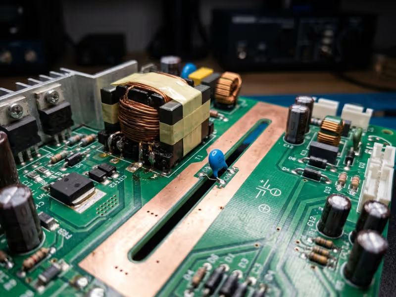
Isolation Design: Capacitance Becomes the Real Enemy
Both ratings need a solid barrier between mains and the patient, usually 2x MOPP at 4,000 VAC with 8 mm creepage.
CF adds a second problem: capacitance across the barrier. Run the mains-on-applied-part math at 264 VAC and 60 Hz. To stay under 50 µA, you get roughly 500 pF of total coupling capacitance. BF typically allows far more margin.
That small number drives real choices:
- Low-capacitance isolation transformers, often physically larger
- Digital isolators instead of high-capacitance optocouplers
- Wider slots and keep-out zones under the barrier
- Fewer or smaller Y-capacitors across the gap
Cost, Size, Sourcing, and Validation Effort
CF pressure spreads well beyond the patient circuit.
- Sourcing narrows. Far fewer vendors publish leakage data tight enough for a CF budget.
- Cost climbs. Specialty magnetics, isolators, and extra board area add to the BOM.
- EMC gets harder. Smaller Y-capacitors mean less common-mode filtering.
- Validation stretches. A failed CF leakage test often forces a layout respin, not a quick part swap.
Comparison Factor | BF | CF | Why It Matters |
|---|---|---|---|
Intended patient contact | Body surface, peripheral access | Direct or indirect path to the heart | Sets the rating before anything else |
Leakage tolerance | 100 µA normal / 500 µA fault | 10 µA normal / 50 µA fault | Defines your full system budget |
Isolation burden | 2x MOPP, moderate capacitance limits | 2x MOPP plus very low barrier capacitance | Drives transformer and isolator choices |
Design complexity | Standard isolated front end | Tight layout, careful part selection | Affects engineering hours and respin risk |
Size / space pressure | Moderate | High, due to wider barriers and bigger magnetics | Can push enclosure size up |
Cost / lead time | Broad supplier base, shorter lead times | Fewer qualified sources, longer lead times | Shapes BOM cost and supply resilience |
Typical applications | NIBP, SpO2, TENS | Intracardiac catheters, pacing leads, IBP lines | Quick sanity check for your classification |
Why “Higher Rated” Doesn’t Mean “Better Choice”
Some teams pick CF as a safety buffer. It rarely pays off.
If no current path can reach the heart, CF limits don’t lower real patient risk. They add cost, board space, EMC trouble, and test time. Cutting Y-capacitance to chase CF numbers can also weaken EMC immunity, which creates a different safety problem.
Match the rating to the patient current path. That protects both the patient and your schedule.
How to Classify Your Device Correctly
Classification stays abstract until you put it on paper. I run this three-step routine with clients before the first schematic review.
Step 1: Map Every Applied Part and Patient Contact Point
Build a table with one row per applied part:
- Part name: ECG lead set, SpO2 clip, IBP transducer
- Body site: finger, chest, radial artery, right atrium
- Contact type: intact skin, mucosa, blood path, or intracardiac
- Accessories accepted: every cable, probe, and adapter the port allows
- Target rating: BF or CF
Look beyond the obvious probes. Handles and patient-side housings may count as applied parts, too. One device can carry several ratings, so mark each port separately.
Step 2: Trace the Full Conductive Path, Not Just the Probe Tip
Start at the tissue and walk backward toward mains.
- List every conductor, including saline columns, guidewires, shields, and connector pins.
- Mark each barrier, with its MOPP level and coupling capacitance.
- Find shared grounds. If ECG and IBP share one isolated ground, the CF limit governs both in practice.
- Check external connections. USB, Ethernet, and nurse call lines all create paths.
Sketch one page per applied part. Circle any path with a weak barrier. That circle shows where your redesign effort should go.
Step 3: Check Normal Condition and Single Fault Condition Separately
Treat these as two separate test plans.
Normal condition: Run at 110% of the highest rated mains voltage, such as 264 VAC for a 240 V rating. Test both polarities and every operating mode. Record patient leakage, patient auxiliary current, and total patient leakage (BF: 500 µA; CF: 50 µA).
Single fault condition: Apply one fault at a time:
- Open the protective earth
- Open one supply conductor
- Apply mains voltage to the applied part
- Apply mains voltage to signal input and output ports
Test at least three prototypes, and record the worst reading, not an average. If a result lands near the limit, fix the barrier. Don’t tweak the fixture until the number looks better.
What the Power Supply Can and Cannot Solve
A medical PSU does a lot of work in a BF or CF design, but it can’t carry the whole device. I sort the work into two groups before reviewing any schematic.
Where a BF- or CF-Capable Supply Earns Its Place
A good supply forms your first and strongest barrier against mains. It gives you:
- 2x MOPP isolation, typically 4,000 VAC with 8 mm creepage
- Low leakage of its own, which leaves most of your budget for the rest of the system
- Low input-to-output capacitance, which matters most in the CF mains-on-applied-part test
The PSU makes the problem smaller. It doesn’t make it disappear.
What Still Depends on Your System Design
Your lab measures current at the patient, not at the supply output. You own everything in between:
- Signal-path barriers: isolated DC-DC converters and digital isolators sized for the target rating
- Shared grounds: one CF channel can impose CF limits on its neighbors
- Accessories: long shielded cables can add several microamps alone
- External ports: a connected laptop or printer can push a clean device over the limit
- Chassis paths: brackets and earthed shields can couple leakage through stray capacitance
Why Supplier Claims Need Proof
“BF-rated” on a product page is a claim, not a test result. Before a supply makes my shortlist, I ask for:
- Measured leakage at 264 VAC, in normal and single-fault conditions, both polarities
- The test conditions, including load, mounting, and earth connection
- A full IEC 60601-1 CB test report, plus its conditions of acceptability
Suppliers with in-house testing and validation can usually share this data quickly and explain the setup behind each number. If a vendor sends only a certificate, keep asking.
Common Mistakes That Cause Rework
Most BF and CF rework starts with an early assumption nobody checks. These four come up most often in my project reviews.
Assuming CF Is Always the Safer Default
If no path reaches the heart, CF doesn’t make the patient safer. It just shrinks your capacitance budget and complicates EMC.
One client chose CF for a surface-only therapy device “just in case.” They spent eleven weeks fixing conducted emissions, then switched back to BF.
Treating Skin Contact as Automatic BF Without Tracing Fault Paths
“It only touches skin” describes the probe tip, not the whole path. A shared isolated ground or a cath-lab setting can change the answer.
Normal-condition tests hide these issues. Single faults expose them. Skip this step, and the lab will run it for you.
Trusting a Marketing Label Without Reviewing Compliance Evidence
A value measured at 230 VAC can climb past the limit at 264 VAC. Some vendors quote earth leakage instead of touch or patient current.
Read the full CB report. Check measured values, test setup, and conditions of acceptability. A certificate proves a test happened. The report shows whether it fits your design.
Thinking the Power Supply Rating Alone Determines Device Classification
“We use a BF supply, so the device is BF” runs backward. IEC 60601-1 classifies applied parts, not power supplies.
Classify each applied part first. Then confirm the full system holds that limit. Treat the supply rating as supporting evidence, not the answer.
A Practical Selection Workflow for Engineers
Good BF and CF decisions follow a fixed order. I hand clients this workflow at kickoff and ask them not to skip ahead.
Step | What to Confirm | Why It Matters |
|---|---|---|
1. Define each applied part | Body site, contact type, and every accessory each port accepts | Ratings apply per applied part. One “compatible” lead can change the answer. |
2. Identify possible cardiac pathways | Saline columns, guidewires, pacing leads, shared grounds, use beside intracardiac devices | One cardiac path moves that part into CF territory. The normal limit drops from 100 µA to 10 µA. |
3. Evaluate leakage under normal and single-fault conditions | Patient, auxiliary, and total patient leakage at 110% of rated mains, both polarities | Fault tests expose weak barriers that clean bench tests hide. |
4. Verify the architecture can hold the required isolation | 2x MOPP, total barrier capacitance (roughly 500 pF for CF), isolated front end, ports, chassis paths | A strong PSU can’t fix an unisolated USB port or a shared ground. |
5. Shortlist suppliers only after classification is clear | Leakage at 264 VAC, input-to-output capacitance, full CB report, second source | You compare real data, not labels, and avoid paying for CF when BF fits. |
Three habits make this workflow stick:
- Turn each step into a signed record. Your risk file will need it.
- Loop back, not forward. If step 4 fails, return to step 2. You likely missed a pathway.
- Revisit at every design change. I’ve seen one added IBP option turn a clean BF monitor into a CF project.
FAQs
What is the main difference between BF and CF medical power supplies?
The difference lies in the leakage limits they help your device meet. BF supports body-surface parts: 100 µA normal, 500 µA under a single fault. CF supports parts with a possible path to the heart: 10 µA normal, 50 µA under a fault. Strictly, these ratings belong to applied parts.
Can a BF-rated power supply be used in a cardiac application?
Sometimes. The numbers matter more than the label. If the supply has 2x MOPP, very low leakage, and low barrier capacitance, your system may still reach CF limits, provided your isolated front end carries most of the barrier.
Does a CF-rated power supply make the whole device CF-rated?
No. Shared grounds, long leads, USB ports, and chassis paths can each push the total past 10 µA. A CF-capable supply gives you margin. Your system design still has to earn the rating.
When does skin-contact equipment still require deeper analysis?
Dig deeper when the port accepts invasive accessories, a surface channel shares ground with a CF channel, the device runs during cardiac procedures, or the probe sits near the heart.
Which standard defines BF and CF classifications?
IEC 60601-1 defines them, along with leakage limits and test methods. Collateral and particular standards, such as IEC 60601-1-11 and IEC 60601-2-27, can add device-specific requirements.
Is CF always more expensive and harder to source?
Usually, but not always. A supplier with an existing low-leakage platform can close much of the gap. Compare full test reports, lead times, and validation effort, not just unit price.
Start With the Patient, Then Pick the Supply
BF and CF don’t rank as “good” and “better.” They answer one question: can patient current reach the heart? If it can, you are in CF territory. If every path stops at the body surface, BF usually fits.
Follow this order:
- Classify each applied part, including every accessory its port accepts.
- Trace the full protection path, then test normal and single-fault conditions.
- Then compare suppliers and cost, using measured leakage and full CB reports.
Get step one wrong, and everything downstream drifts. You pick the wrong supply, validate against the wrong limits, and bring a risk file to the lab that can’t hold up.
Get it right, and the supply decision becomes simple. When you reach the shortlist stage, browse the full AC-DC power supply range to compare platforms side by side.