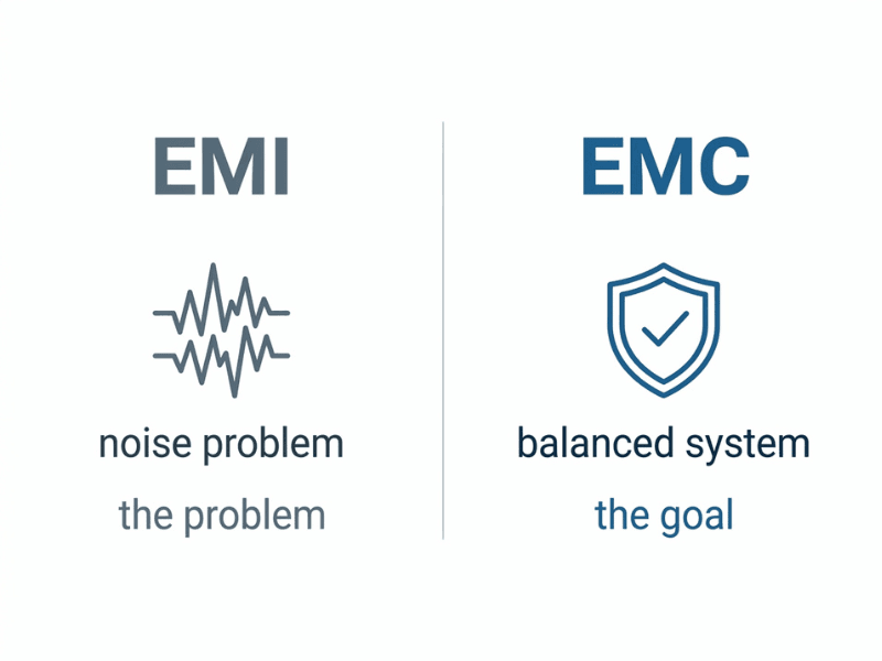
EMI (electromagnetic interference) refers to the noise a power supply generates or experiences. EMC (electromagnetic compatibility) is the broader engineering goal—ensuring a device neither pollutes its environment with EMI nor malfunctions when exposed to it. Both concepts are closely linked but serve distinct roles in power supply design and compliance.
Every switching power supply is, by nature, a noise generator. High-frequency switching transitions, fast-changing currents, and parasitic elements all create electromagnetic disturbances that can disrupt nearby electronics, cause regulatory test failures, or degrade system performance. Understanding how to manage those disturbances is central to professional power supply design.
That’s where EMI and EMC come in. The two terms often appear together, and in casual conversation they’re sometimes used interchangeably. But they describe different things—and confusing them can lead to design decisions that miss the mark.
This guide cuts through the ambiguity. It covers the precise definitions of EMI and EMC, how noise travels through and around a power supply, what engineers can do to control it, and which regulatory standards apply in different industries. Whether you’re designing a new AC/DC supply or troubleshooting a compliance failure, the principles here apply directly.
Why Do EMI and EMC Get Confused?
Part of the problem is definitional inconsistency. Even the International Electrotechnical Commission (IEC), the body that sets global electrical standards, acknowledges that the two terms overlap in common usage.
The IEC defines EMC as the “ability of equipment or a system to function satisfactorily in its electromagnetic environment without introducing intolerable electromagnetic disturbances to anything in that environment.” In plain terms: don’t cause problems for others, and don’t be disrupted by them.
EMI, by contrast, is defined by the IEC as “degradation in the performance of equipment or transmission channel or a system caused by an electromagnetic disturbance.” It’s the disruption itself—not the property of tolerating it.
So EMI is the problem. EMC is the goal. The two are deeply connected, but the distinction matters when you’re deciding what to test, what to fix, and what compliance path to follow.
What is Electromagnetic Interference (EMI) in a Power Supply?
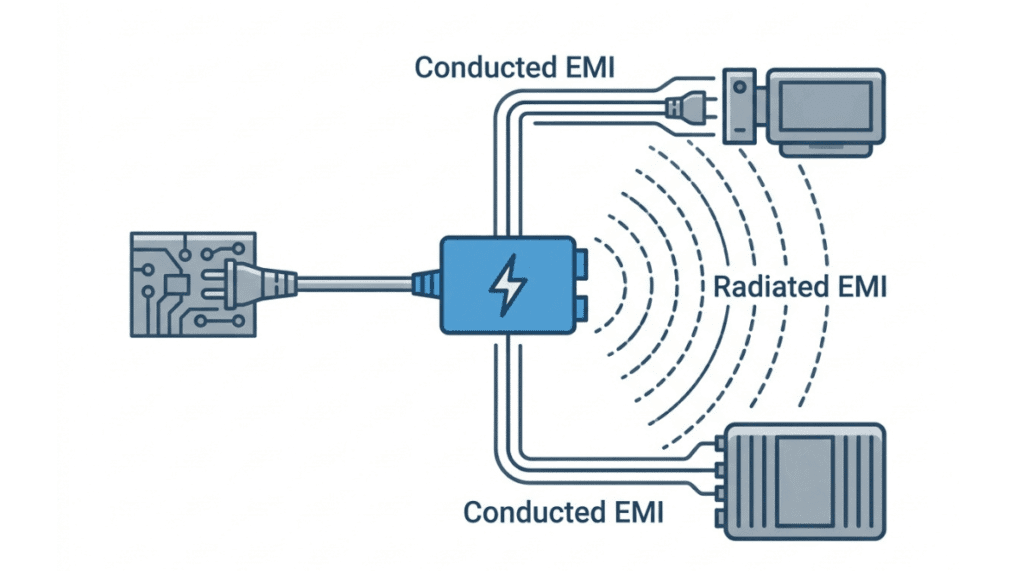
Switching power supplies are particularly prolific sources of EMI. The rapid switching of transistors produces high dV/dt and dI/dt, generating broadband noise across a wide frequency spectrum. That noise exists in the supply through two primary pathways: conduction along power lines and radiation through the air.
Conducted Emissions
Conducted emissions travel from the power supply back to the AC mains through the input power conductors. Regulatory agencies regulate this in the frequency range of 150 kHz to 30 MHz.
To measure conducted emissions, a line impedance stabilization network (LISN) is inserted between the power source and the device under test. The LISN provides a standardized impedance environment and a measurement port to quantify the noise returned to the mains.
Power supplies typically include input EMI filters to suppress conducted emissions. However, when the supply is integrated into a larger system, noise from the system load can propagate back through the supply and appear at the input. System-level compliance testing often reveals this, requiring the system engineer to add additional filtering.
Radiated Emissions
Radiated emissions travel through space as electromagnetic waves. These are regulated from 30 MHz to 1 GHz (and above for some standards). Any conductor connected to the power supply—input cables, output cables, chassis wiring—can act as an unintentional antenna, radiating energy.
Radiated emissions are measured using broadband antennas in an anechoic chamber, with horizontally and vertically polarized measurements taken at specified distances.
One practical challenge: radiated emissions don’t just come from the power supply itself. They can result from the interaction between the supply and the system load. A supply that passes standalone radiated emissions testing may still cause problems once integrated.
Harmonic Currents
For AC-powered supplies, there’s a third category: harmonic distortion. A bridge rectifier with a bulk capacitor draws current in narrow pulses near the peak of the AC voltage waveform, rather than following the sinusoidal input smoothly. The resulting pulsed current contains significant energy at harmonic multiples of the line frequency (50 or 60 Hz).
This distorts the power grid and creates transmission inefficiencies. IEC 61000-3-2 sets limits on harmonic current emissions from the 2nd through the 40th harmonic, and applies to equipment with a rated input current of up to 16 A per phase. Power Factor Correction (PFC) circuits are used in many power supplies specifically to reshape the input current waveform and bring harmonic content within limits.
What is Electromagnetic Compatibility (EMC)?
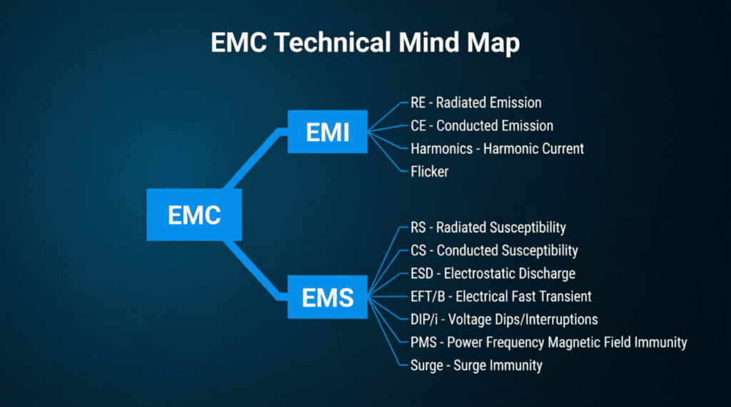
EMC has two sides. One is about emissions, which is where EMI lives. The other concerns immunity: can the power supply (and the system it’s part of) continue to function correctly when subjected to external electromagnetic disturbances?
The immunity side covers a range of standardized test conditions:
- Electrostatic Discharge (ESD): A discharge event caused by interaction with the operating environment, such as a human touching the equipment.
- Electrical Fast Transients (EFT): Bursts of fast, repetitive voltage spikes coupled onto power or signal lines, typically caused by switching of inductive loads.
- Surge: High-energy transients caused by events like lightning strikes or large inductive load switching on the grid.
- Voltage Dips and Interruptions: Short-duration drops or complete loss of input voltage.
Power supplies and their associated systems must be designed and tested to demonstrate acceptable performance under all these conditions. Immunity limits are set by the IEC 61000-4 series, which includes separate test procedures for each disturbance type.
Achieving EMC, then, means satisfying two obligations simultaneously: minimizing the noise you generate and tolerating the noise you’re exposed to.
How Noise Transfers: Coupling Mechanisms in Power Supplies
Understanding how EMI propagates helps engineers choose the right mitigation strategy. There are four fundamental coupling mechanisms.
Conducted and Radiated Coupling
Conducted coupling occurs when noise travels along a shared electrical path—such as a power cable, a ground conductor, or a signal return. This is the primary mechanism for conducted emissions and immunity disturbances.
Radiated coupling occurs when electromagnetic energy propagates through space and is picked up by a physically separate circuit. This becomes the dominant mechanism above 30 MHz, where wavelengths are short enough that ordinary PCB traces and cables become efficient antennas.
Capacitive and Inductive Coupling
Capacitive coupling occurs when a changing voltage on one conductor induces a current in an adjacent conductor through parasitic capacitance. The coupling intensity depends on frequency, conductor spacing, the impedance of the victim circuit, and the dielectric between the conductors.
In power supplies, capacitive coupling is a key source of common-mode noise. The switching node—where voltage transitions rapidly between rail and ground—can couple energy to the chassis or other conductors through the parasitic capacitance between the switch node copper and the surrounding ground plane.
Inductive coupling occurs when a changing current in one conductor induces a voltage in another through mutual inductance. It follows the principle of electromagnetic induction: any loop carrying a time-varying current generates a magnetic field, and any nearby loop that intercepts that field will experience an induced voltage.
Large current loops in PCB layout create strong magnetic fields. Minimizing loop area is one of the most effective layout-level EMI controls available.
Common Mode vs. Differential Mode Noise
This distinction is critical for filter design. Getting it wrong wastes time and money.
Differential mode (DM) noise appears between the supply and return lines—the two conductors carry equal and opposite noise currents. DM noise tends to dominate at lower frequencies and is primarily caused by the switching ripple current circulating in the power stage.
Common mode (CM) noise appears between both supply conductors and ground simultaneously—the noise current flows in the same direction on both lines and returns via the ground or chassis. CM noise is caused by parasitic capacitance from high dV/dt nodes to ground (CSTRAY) and tends to dominate at higher frequencies.
According to research published by Analog Devices (2021), in a typical buck converter, DM noise dominates the conducted emissions spectrum at lower frequencies while CM noise dominates at higher frequencies. Identifying which mode is responsible for a compliance failure directs the engineer toward the correct fix. A DM filter does little to suppress CM noise, and vice versa.
How Engineers Control EMI to Achieve EMC
EMC compliance is rarely an accident. It comes from deliberate design choices made early in the development process.
Shielding
A metallic enclosure around a power supply interrupts the radiation path between the switching circuitry and the external environment. Shielding is most effective for radiated emissions and immunity. The effectiveness depends on the conductivity of the shield material, the frequency of the noise, and—critically—the integrity of the seams, apertures, and connector penetrations.
EMI Filters
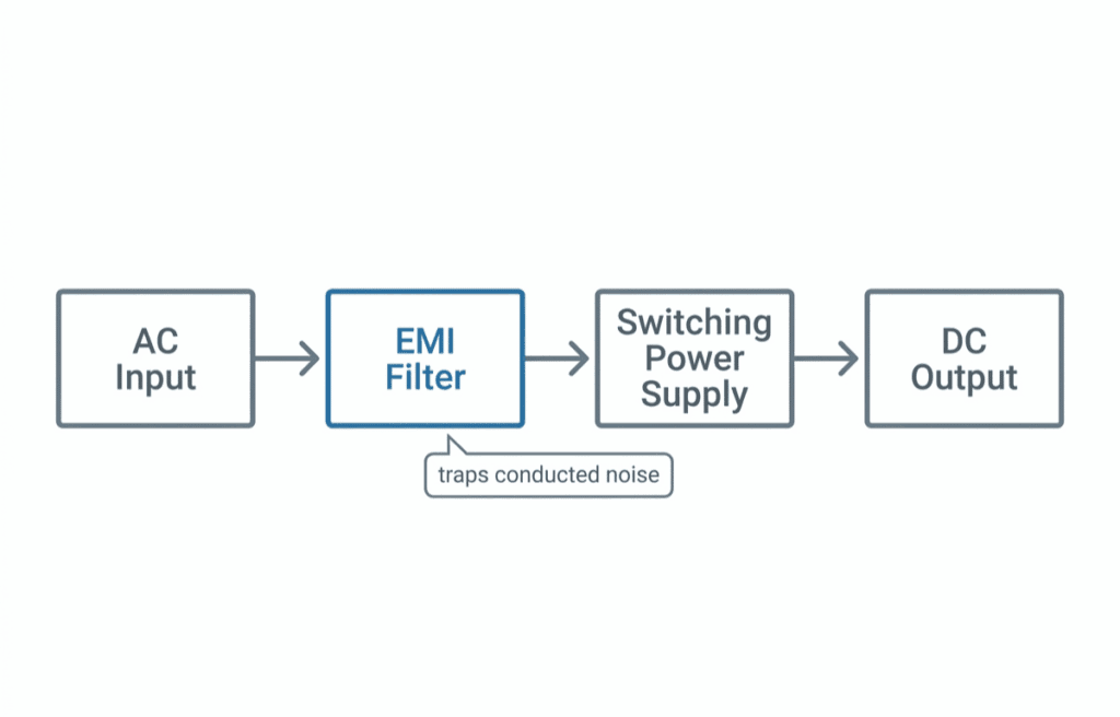
Input EMI filters use combinations of inductors and capacitors to block noise from traveling onto the power mains. X-capacitors (connected line-to-line) attenuate differential mode noise. Y-capacitors (connected line-to-ground) attenuate common-mode noise. Common mode chokes—wound on a shared core—present high impedance to CM currents while passing differential power currents with minimal loss.
The filter topology must be matched to the noise profile. If CM noise is the primary compliance challenge, a CM choke and Y-capacitors are the right tools. If DM noise is the problem, X-capacitors and DM inductors are more effective.
PCB Layout
Good layout is often more effective than added components—and cheaper. Key practices include:
- Minimize switching node copper area. The switch node is the point in the circuit where dV/dt is highest. Reducing its copper area reduces CSTRAY and lowers CM noise at the source.
- Keep high-frequency current loops small. The smaller the area enclosed by a high-frequency current path, the weaker its radiated magnetic field.
- Use a solid ground plane. A continuous ground plane provides a low-impedance return path for high-frequency currents and reduces noise coupling between sections of the board.
- Separate noisy and quiet sections. Power-stage components and output rectifiers should be physically separated from the control circuitry and signal paths.
Component Selection and Gate Resistors
Increasing the gate resistance on switching transistors slows the switching transitions, reducing dV/dt and dI/dt. This lowers the high-frequency content of the switching waveform. The trade-off is slightly higher switching losses, so gate resistance is typically tuned to find the acceptable balance between EMI and efficiency.
Soft-switching topologies—zero-voltage switching (ZVS) and zero-current switching (ZCS)—take this further by arranging circuit operation so that transistors switch at the moment voltage or current is near zero. This dramatically reduces switching losses and EMI simultaneously.
Twisted Pair Wiring
For power supply output wiring or inter-board connections, twisting the positive and return conductors together cancels the magnetic fields generated by the differential current. Each half-twist reverses the field’s orientation, causing successive fields to cancel. Twisted pair is a simple, low-cost tool for reducing inductive coupling and radiated emissions from wiring harnesses.
Regulatory Standards That Apply to Power Supplies
Compliance requirements depend on the end market and application. Here’s a practical overview of the standards engineers encounter most often.
Standard | Market | Scope |
|---|---|---|
FCC Part 15 | United States | Unintentional radiators: Class A (commercial), Class B (residential) limits |
CISPR 32 / EN 55032 | Global / EU | Multimedia equipment; replaced CISPR 22 |
CISPR 11 | Global | Industrial, scientific, and medical (ISM) equipment |
IEC 61000-3-2 | Global | Harmonic current emissions; applies to equipment ≤16 A |
IEC 61000-4 series | Global | Immunity testing (ESD, EFT, surge, RF) |
IEC 60601-1-2 | Medical | EMC for medical electrical equipment; stricter immunity requirements |
MIL-STD-461 | US Military / Aerospace | Conducted and radiated emissions and susceptibility; applies to military equipment and subsystems |
A few points worth highlighting. IEC 60601-1-2 applies to power supplies used in medical devices and carries more stringent immunity requirements than general commercial standards—because a pacemaker or infusion pump that malfunctions due to EMI poses a direct patient safety risk. MIL-STD-461 has been in use since 1967 and covers a broad range of emissions and susceptibility tests across frequency ranges that exceed typical commercial requirements.
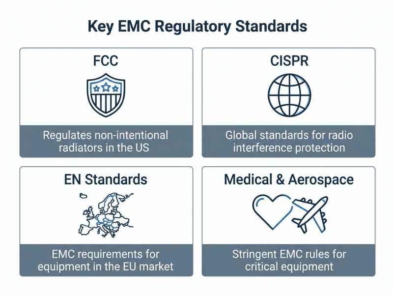
For commercial products sold in both the US and EU, compliance with both FCC Part 15 and the relevant EN standard (such as EN 55032) is typically required.
Frequently Asked Questions About EMI and EMC in Power Supplies
What is the core difference between EMI and EMC?
EMI is electromagnetic interference—the noise a device generates or is affected by. EMC is electromagnetic compatibility—the engineering property of operating without causing or being disrupted by that noise. EMC compliance requires managing both emissions (like EMI) and immunity.
Do all power supplies need EMC testing?
Any power supply sold in regulated markets (US, EU, and most others) must comply with the applicable EMC standard for its end application. The specific standard depends on the product category and the market. Medical and defense applications have their own distinct requirements beyond general commercial standards.
What is the difference between common-mode and differential-mode noise?
Differential-mode noise appears between the positive and return conductors and is typically caused by switching-induced ripple currents. Common-mode noise appears between both conductors and ground and is caused by parasitic capacitance at high-dV/dt switching nodes. DM noise dominates at lower frequencies; CM noise at higher frequencies. Each requires different filter components to suppress.
What is a LISN, and why is it used for conducted emissions testing?
A Line Impedance Stabilization Network (LISN) is placed between the AC power source and the device under test during conducted emissions measurements. It provides a standardized 50 Ω impedance to the measurement instrument and isolates the DUT from mains-borne noise that would otherwise distort the measurement.
Which is more cost-effective: designing for EMC early or fixing compliance failures late?
Designing for EMC from the outset is significantly cheaper. Layout changes, filter component additions, and shielding retrofits are straightforward during development. After prototypes are built, EMC fixes typically involve costly respins, schedule delays, and expedited testing fees. Starting with a solid EMC strategy—good layout, appropriate filtering, and realistic pre-compliance screening—pays for itself quickly.
When do I need Power Factor Correction in my power supply?
PFC is generally required when the equipment draws more than a certain level of harmonic current from the mains. IEC 61000-3-2 defines the applicable limits. Equipment with a rated input current up to 16 A and connected to the public low-voltage mains typically needs to comply. Many commercial AC/DC power supplies above roughly 75 W include active PFC to meet these requirements.
Design for EMC: From the First Schematic
The most expensive place to solve an EMC problem is during a pre-production prototype phase, days before a compliance test. The least expensive place is in the initial schematic and layout—before a single board is built.
That means considering noise coupling mechanisms during topology selection, planning the PCB stackup and ground plane before routing begins, sizing filter components based on the expected noise profile, and running pre-compliance checks throughout development rather than only at the end.
EMI and EMC are not afterthoughts. They’re intrinsic to how switching power supplies behave, and managing them is part of the core design discipline. A supply that passes emissions testing, withstands immunity testing, and operates cleanly within its system isn’t just compliant—it’s a better-engineered product.